Chapter 2: Overview
2.4Hardware Description 2.4.1 LGB5028A
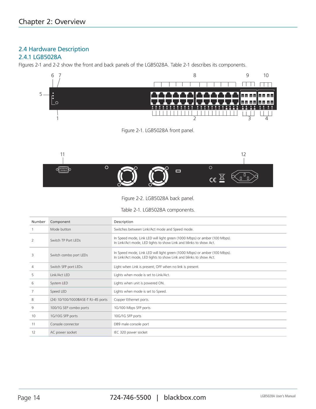
FIgures |
|
|
|
|
|
|
|
|
| ||||||||||||||||||||||||||||||||||
6 | 7 |
|
|
|
|
|
|
|
|
|
|
|
| 8 |
|
|
|
|
|
|
|
|
|
|
|
|
| 9 |
|
|
|
| 10 |
|
|
| |||||||
5 |
|
|
|
|
|
|
|
|
|
|
|
|
|
|
|
|
|
|
|
|
|
|
|
|
|
|
|
|
|
|
|
|
|
|
|
|
|
|
|
|
|
|
|
|
|
|
|
|
|
|
|
|
|
|
|
|
|
|
|
|
|
|
|
|
|
|
|
|
|
|
|
|
|
|
|
|
|
|
|
|
|
|
|
|
|
| |
|
|
|
|
|
|
|
|
|
|
|
|
|
|
|
|
|
|
|
|
|
|
|
|
|
|
|
|
|
|
|
|
|
|
|
|
|
|
|
|
|
|
| |
|
|
|
|
|
|
|
|
|
|
|
|
|
|
|
|
|
|
|
|
|
|
|
|
|
|
|
|
|
|
|
|
|
|
|
|
|
|
|
|
|
|
| |
|
|
|
|
|
|
|
|
|
|
|
|
|
|
|
|
|
|
|
|
|
|
|
|
|
|
|
|
|
|
|
|
|
|
|
|
|
|
|
|
|
| ||
|
|
|
|
|
|
|
|
|
|
|
|
|
|
|
|
|
|
|
|
|
|
|
|
|
|
|
|
|
|
|
|
|
|
|
|
|
|
|
|
|
|
| |
|
|
|
|
|
|
|
|
|
|
|
|
|
|
|
|
|
|
|
|
|
|
|
|
|
|
|
|
|
|
|
|
|
|
|
|
|
|
|
|
|
|
|
|
|
|
|
|
|
|
|
|
|
|
|
|
|
|
|
|
|
|
|
|
|
|
|
|
|
|
|
|
|
|
|
|
|
|
|
|
|
|
|
|
|
|
|
|
|
|
|
|
|
|
|
|
|
|
|
|
|
|
|
|
|
|
|
|
|
|
|
|
|
|
|
|
|
|
|
|
|
|
|
|
|
|
|
|
|
|
|
|
|
|
|
| 25 | 26 | 27 | 28 | 29 | 30 | 31 | 32 | 33 | 34 | 35 | 36 | 37 | 38 | 39 | 40 | 41 | 42 | 43 | 44 | 45 | 46 | 47 | 48 | 47 | 48 |
| 47 | 48 |
| 40 | 50 | 51 | 52 |
|
| ||||
|
|
|
|
|
|
|
|
|
|
|
|
|
|
|
|
|
|
|
|
|
|
|
|
|
|
|
|
|
|
|
|
|
|
|
|
|
|
|
|
|
|
|
|
1 |
|
|
|
|
|
|
|
|
|
|
|
|
|
|
|
|
|
|
|
|
|
|
|
|
|
|
|
|
|
|
|
|
|
|
| 2 |
|
|
|
|
|
|
|
|
|
| |
| Figure | ||||||||||||||||||||||
3
4
11 | 12 | ||
|
|
|
|
|
|
|
|
|
| Figure | |
|
| Table | |
|
|
| |
Number | Component | Description | |
|
|
| |
1 | Mode button | Switches between Link/Act mode and Speed mode. | |
|
|
| |
2 | Switch TP Port LEDs | In Speed mode, Link LED will light green (1000 Mbps) or amber (100 Mbps). | |
In Link/Act mode, LED lights to show Link and blinks to show Act. | |||
|
| ||
|
|
| |
3 | Switch combo port LEDs | In Speed mode, Link LED will light green (1000 Mbps) or amber (100 Mbps). | |
In Link/Act mode, LED lights to show Link and blinks to show Act. | |||
|
| ||
|
|
| |
4 | Switch SFP port LEDs | Light when Link is present; OFF when no link is present. | |
|
|
| |
5 | Link/Act LED | Lights when mode is set to Link/Act. | |
|
|
| |
6 | System LED | Lights when unit is powered ON. | |
|
|
| |
7 | Speed LED | Lights when mode is set to Speed. | |
|
|
| |
8 | (24) | Copper Ethernet ports. | |
|
|
| |
9 | 100/1G SEP combo ports | 1G/100 Mbps SFP ports | |
|
|
| |
10 | 1G/10G SFP ports | 10G/1G SFP ports | |
|
|
| |
11 | Console connector | DB9 male console port | |
|
|
| |
12 | AC power socket | IEC 320 power socket | |
|
|
|
Page 14 | LGB5028A User‘s Manual | |
|
|
