•When you have imported a .FPE and a .PNG, .JPG, or .GIF format Coverage Area map, click Save to store the Cisco 1000 Series lightweight access point locations and orientations, and have Cisco WCS compute the
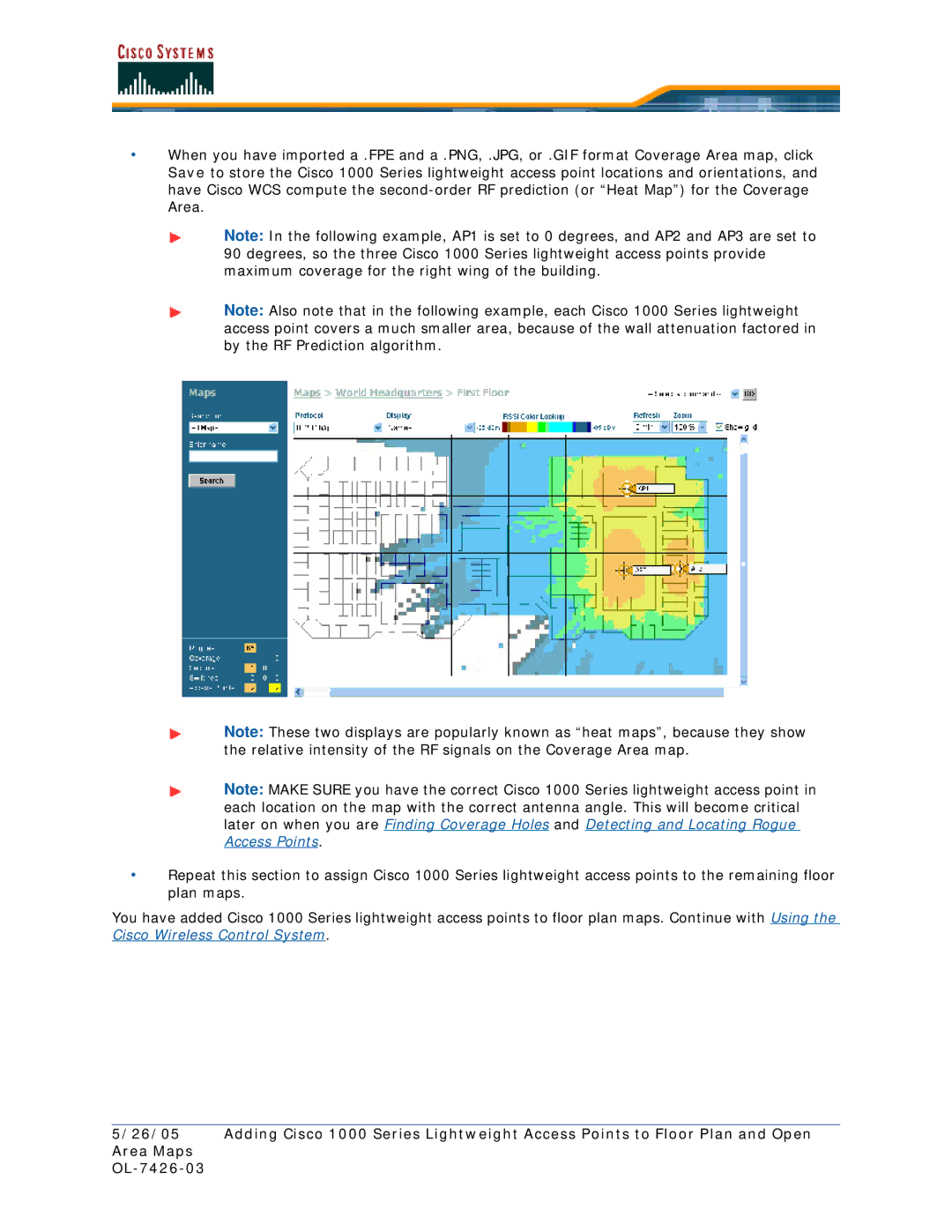
Note: In the following example, AP1 is set to 0 degrees, and AP2 and AP3 are set to 90 degrees, so the three Cisco 1000 Series lightweight access points provide maximum coverage for the right wing of the building.
Note: Also note that in the following example, each Cisco 1000 Series lightweight access point covers a much smaller area, because of the wall attenuation factored in by the RF Prediction algorithm.
Note: These two displays are popularly known as “heat maps”, because they show the relative intensity of the RF signals on the Coverage Area map.
Note: MAKE SURE you have the correct Cisco 1000 Series lightweight access point in each location on the map with the correct antenna angle. This will become critical later on when you are Finding Coverage Holes and Detecting and Locating Rogue Access Points.
•Repeat this section to assign Cisco 1000 Series lightweight access points to the remaining floor plan maps.
You have added Cisco 1000 Series lightweight access points to floor plan maps. Continue with Using the Cisco Wireless Control System.
5/26/05 Adding Cisco 1000 Series Lightweight Access Points to Floor Plan and Open Area Maps