Optical-unit drive gear/motor assembly
1Remove the following assemblies:
•glass. See “Glass” on page 92.
•optical unit. See “Optical unit” on page 95.
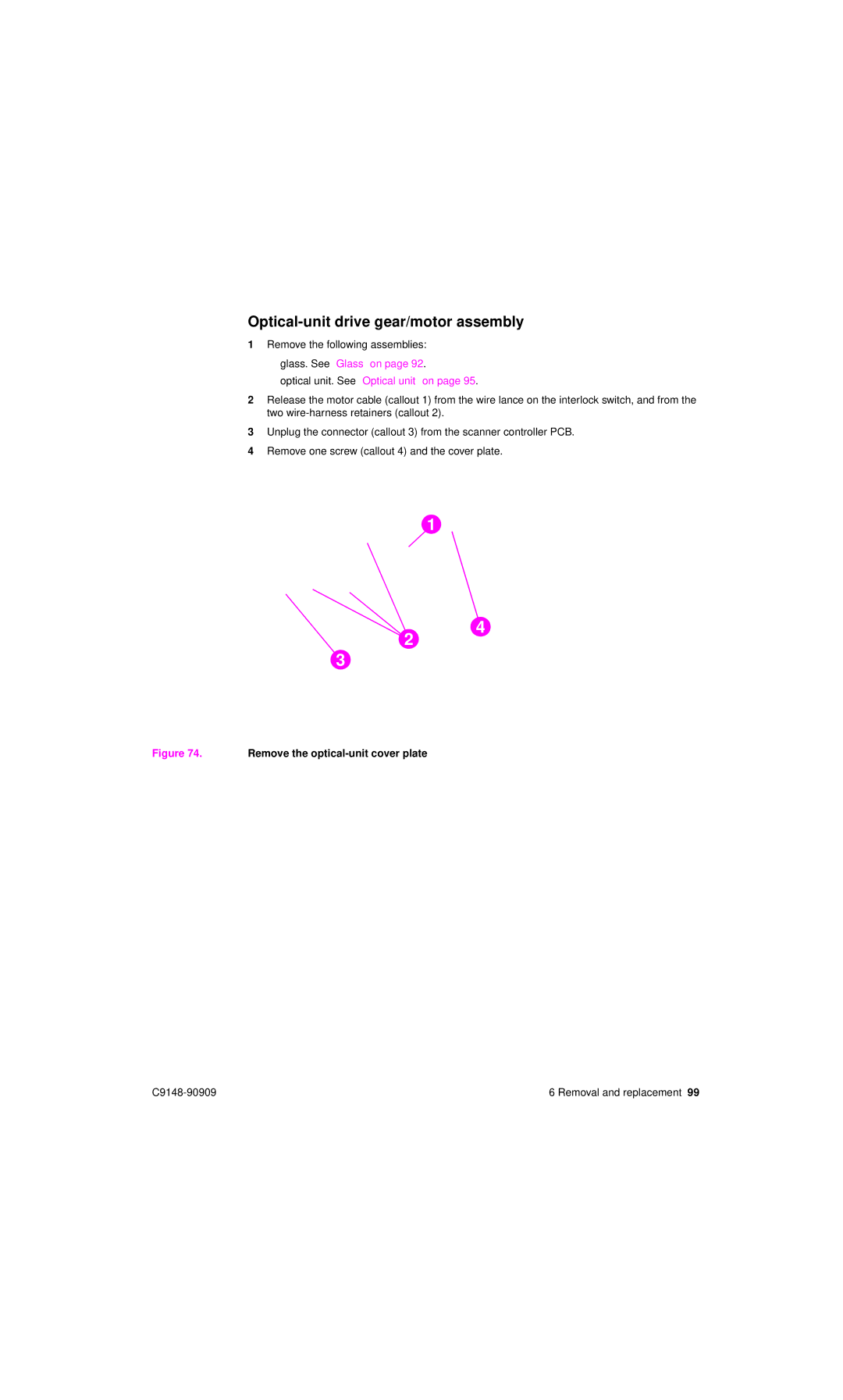
2Release the motor cable (callout 1) from the wire lance on the interlock switch, and from the two
3Unplug the connector (callout 3) from the scanner controller PCB.
4Remove one screw (callout 4) and the cover plate.
1
4
2
3
Figure 74. Remove the optical-unit cover plate
6 Removal and replacement 99 |