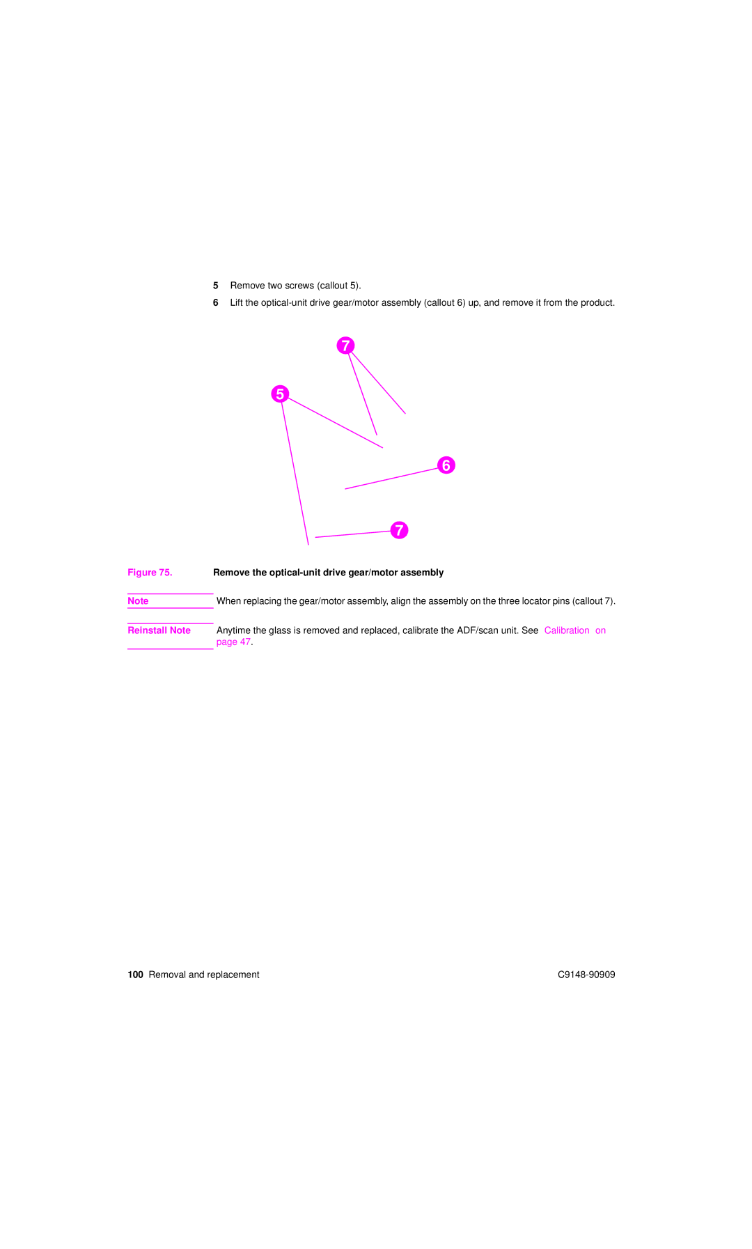
5Remove two screws (callout 5).
6Lift the
7
5
6
7
Figure 75. Remove the optical-unit drive gear/motor assembly
NoteWhen replacing the gear/motor assembly, align the assembly on the three locator pins (callout 7).
Reinstall Note Anytime the glass is removed and replaced, calibrate the ADF/scan unit. See “Calibration” on page 47.
100 Removal and replacement |