Optical unit
1Remove the following assemblies:
•glass. See “Glass” on page 92
•scanning lamp. See “Scanning lamp” on page 93.
CAUTION
CAUTION
Do not touch the mirror, because fingerprints will affect print quality.
It is important to note the routing and placement of the
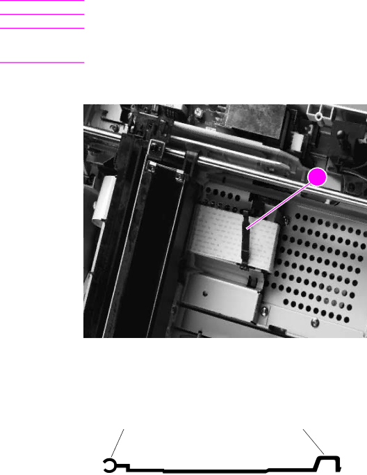
2Open the cable clip (callout 1) and disconnect the
.
1
Figure 67. | Release the optical unit ribbon cable |
|
|
| |
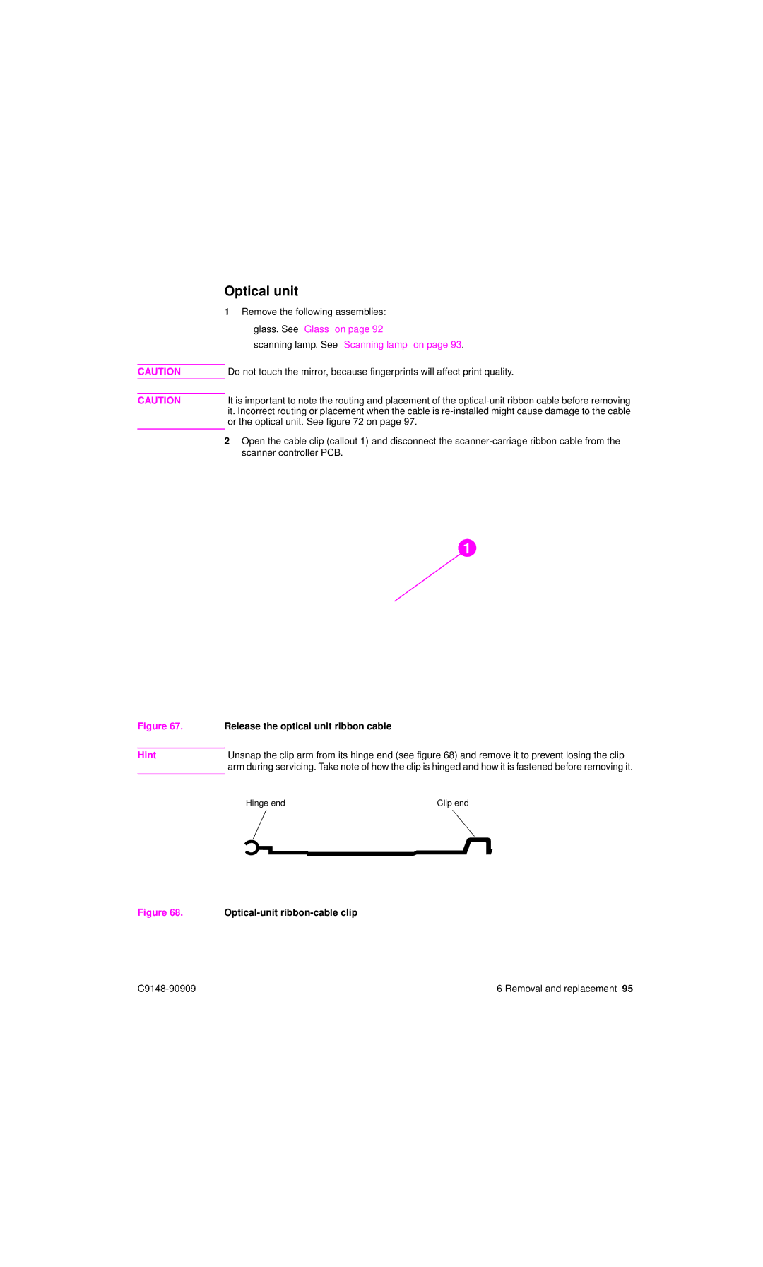
Hint | Unsnap the clip arm from its hinge end (see figure 68) and remove it to prevent losing the clip | |
| arm during servicing. Take note of how the clip is hinged and how it is fastened before removing it. | |
| Hinge end | Clip end |
| ||
4
Figure 68. Optical-unit ribbon-cable clip
6 Removal and replacement 95 |