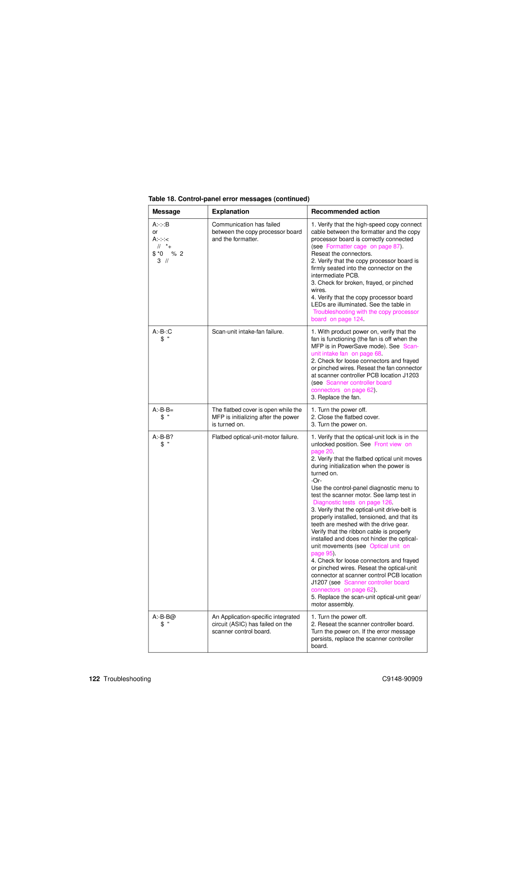
Table 18.
Message | Explanation | Recommended action | |
|
|
|
|
30.0.01 | Communication has failed | 1. | Verify that the |
or | between the copy processor board | cable between the formatter and the copy | |
30.0.02 | and the formatter. | processor board is correctly connected | |
SCANNER I/O |
| (see “Formatter cage” on page 87). | |
FAILURE CHECK |
| Reseat the connectors. | |
COPY CONNECT CARD |
| 2. | Verify that the copy processor board is |
|
| firmly seated into the connector on the | |
|
| intermediate PCB. | |
|
| 3. | Check for broken, frayed, or pinched |
|
| wires. | |
|
| 4. | Verify that the copy processor board |
|
| LEDs are illuminated. See the table in | |
|
| “Troubleshooting with the copy processor | |
|
| board” on page 124. | |
|
|
|
|
30.1.06 | 1. | With product power on, verify that the | |
Scan Failure |
| fan is functioning (the fan is off when the | |
|
| MFP is in PowerSave mode). See “Scan- | |
|
| unit intake fan” on page 68. | |
|
| 2. | Check for loose connectors and frayed |
|
| or pinched wires. Reseat the fan connector | |
|
| at scanner controller PCB location J1203 | |
|
| (see “Scanner controller board | |
|
| connectors” on page 62). | |
|
| 3. | Replace the fan. |
|
|
|
|
30.1.15 | The flatbed cover is open while the | 1. | Turn the power off. |
Scan Failure | MFP is initializing after the power | 2. | Close the flatbed cover. |
| is turned on. | 3. | Turn the power on. |
|
|
|
|
30.1.17 | Flatbed | 1. | Verify that the |
Scan Failure |
| unlocked position. See “Front view” on | |
|
| page 20. | |
|
| 2. Verify that the flatbed optical unit moves | |
|
| during initialization when the power is | |
|
| turned on. | |
|
| ||
|
| Use the | |
|
| test the scanner motor. See lamp test in | |
|
| “Diagnostic tests” on page 126. | |
|
| 3. | Verify that the |
|
| properly installed, tensioned, and that its | |
|
| teeth are meshed with the drive gear. | |
|
| Verify that the ribbon cable is properly | |
|
| installed and does not hinder the optical- | |
|
| unit movements (see “Optical unit” on | |
|
| page 95). | |
|
| 4. | Check for loose connectors and frayed |
|
| or pinched wires. Reseat the | |
|
| connector at scanner control PCB location | |
|
| J1207 (see “Scanner controller board | |
|
| connectors” on page 62). | |
|
| 5. | Replace the |
|
| motor assembly. | |
|
|
|
|
30.1.18 | An | 1. | Turn the power off. |
Scan Failure | circuit (ASIC) has failed on the | 2. | Reseat the scanner controller board. |
| scanner control board. | Turn the power on. If the error message | |
|
| persists, replace the scanner controller | |
|
| board. | |
|
|
|
|
122 Troubleshooting |