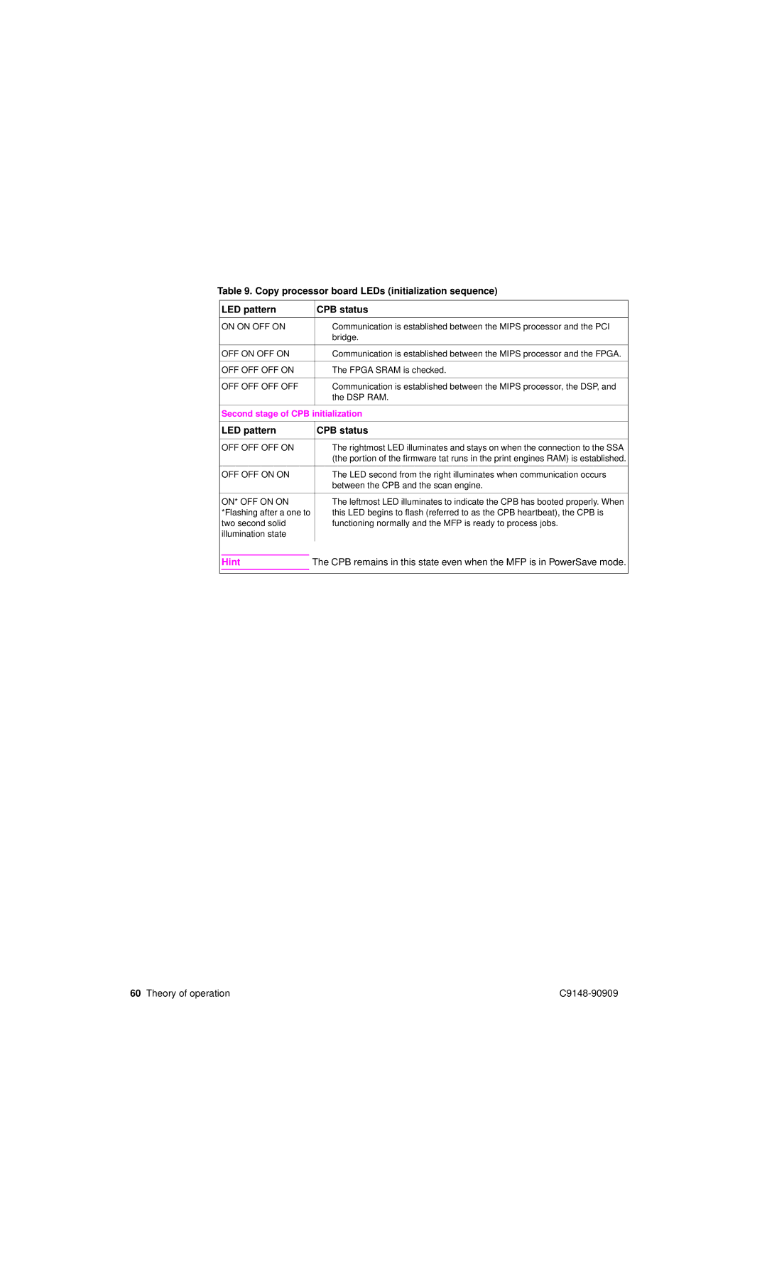
Table 9. Copy processor board LEDs (initialization sequence)
| LED pattern |
| CPB status | |
|
|
|
| |
| ON ON OFF ON |
| ● Communication is established between the MIPS processor and the PCI | |
|
|
|
| bridge. |
|
|
|
| |
| OFF ON OFF ON |
| ● Communication is established between the MIPS processor and the FPGA. | |
|
|
|
| |
| OFF OFF OFF ON |
| ● The FPGA SRAM is checked. | |
|
|
|
| |
| OFF OFF OFF OFF |
| ● Communication is established between the MIPS processor, the DSP, and | |
|
|
|
| the DSP RAM. |
|
|
| ||
| Second stage of CPB initialization | |||
|
|
|
| |
| LED pattern |
| CPB status | |
|
|
|
| |
| OFF OFF OFF ON |
| ● The rightmost LED illuminates and stays on when the connection to the SSA | |
|
|
|
| (the portion of the firmware tat runs in the print engines RAM) is established. |
|
|
|
| |
| OFF OFF ON ON |
| ● The LED second from the right illuminates when communication occurs | |
|
|
|
| between the CPB and the scan engine. |
|
|
|
| |
| ON* OFF ON ON |
| ● The leftmost LED illuminates to indicate the CPB has booted properly. When | |
| *Flashing after a one to |
| this LED begins to flash (referred to as the CPB heartbeat), the CPB is | |
| two second solid |
| functioning normally and the MFP is ready to process jobs. | |
| illumination state |
|
| |
|
|
|
|
|
| Hint | The CPB remains in this state even when the MFP is in PowerSave mode. | ||
|
|
|
|
|
|
|
|
|
|
60 Theory of operation |