Intake fan
1Remove the following assemblies:
•copy processor board (CPB). See “Copy processor board” on page 83.
•glass. See “Glass” on page 92.
•optical unit. See “Optical unit” on page 95.
2Unplug the fan connector from the scanner controller PCB (the
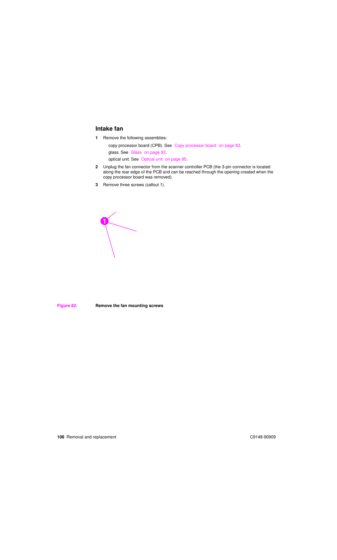
3Remove three screws (callout 1).
1
Figure 82. Remove the fan mounting screws
106 Removal and replacement |