Scanner controller PCB
1Remove the following assemblies:
•copy processor board (CPB). See “Copy processor board” on page 83.
•glass. See “Glass” on page 92
•optical unit. See “Optical unit” on page 95.
•inverter PCB. See “Inverter PCB” on page 103.
CAUTION | The product contains components that are sensitive to electrostatic discharge (ESD). Always |
| perform service work at an |
| available, discharge body static by grasping the print engine chassis before touching an ESD |
| sensitive component. Ground the print engine chassis before servicing the product. |
|
|
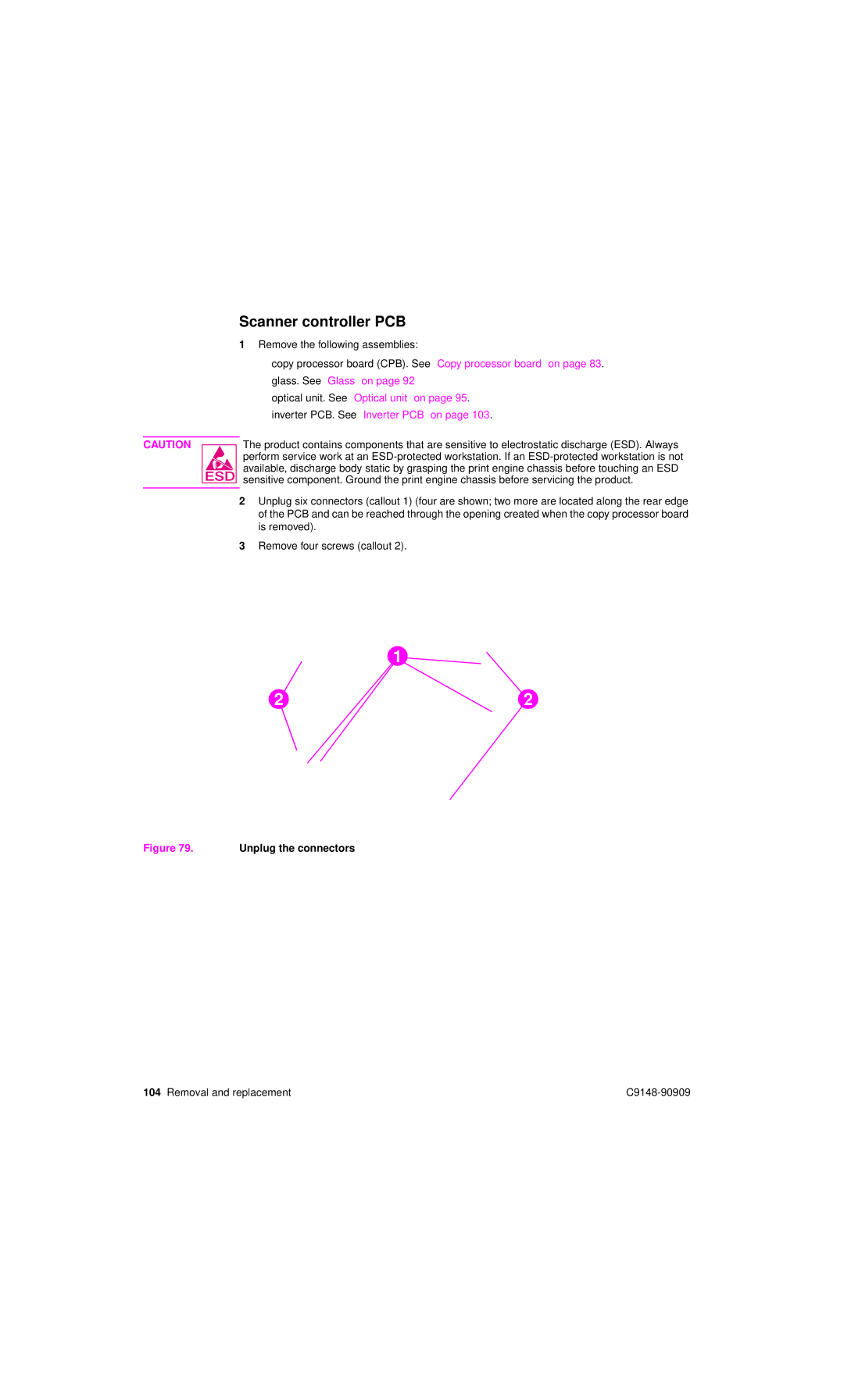
2Unplug six connectors (callout 1) (four are shown; two more are located along the rear edge of the PCB and can be reached through the opening created when the copy processor board is removed).
3Remove four screws (callout 2).
1
2 | 2 |
Figure 79. Unplug the connectors
104 Removal and replacement |