Troubleshooting with the copy processor board
| The table in this section is a quick reference source for troubleshooting common copy processor |
| board (CPB) failures that might occur after or during CPB initialization. The LED pattern column |
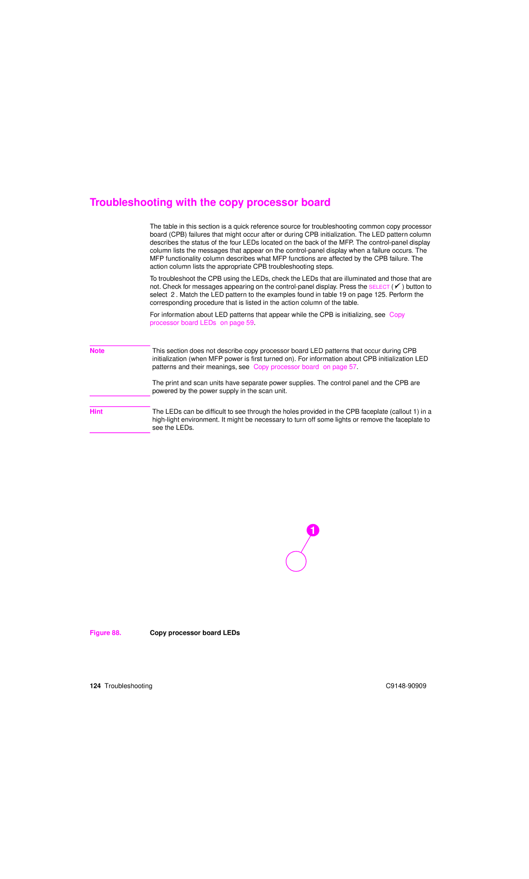
| describes the status of the four LEDs located on the back of the MFP. The |
| column lists the messages that appear on the |
| MFP functionality column describes what MFP functions are affected by the CPB failure. The |
| action column lists the appropriate CPB troubleshooting steps. |
| To troubleshoot the CPB using the LEDs, check the LEDs that are illuminated and those that are |
| not. Check for messages appearing on the |
| select OK. Match the LED pattern to the examples found in table 19 on page 125. Perform the |
| corresponding procedure that is listed in the action column of the table. |
| For information about LED patterns that appear while the CPB is initializing, see “Copy |
| processor board LEDs” on page 59. |
|
|
Note | This section does not describe copy processor board LED patterns that occur during CPB |
| initialization (when MFP power is first turned on). For information about CPB initialization LED |
| patterns and their meanings, see “Copy processor board” on page 57. |
| The print and scan units have separate power supplies. The control panel and the CPB are |
| powered by the power supply in the scan unit. |
|
|
|
|
Hint | The LEDs can be difficult to see through the holes provided in the CPB faceplate (callout 1) in a |
| |
| see the LEDs. |
|
|
1
Figure 88. | Copy processor board LEDs |
|
124 Troubleshooting |
| |
