4Disconnect the
5Carefully lift the fan air duct locking tab (callout 3) and slide the fan shield away (as indicated by the arrow) from the fan, and then remove it.
6Pry the top of the grounding strip (callout 4) out of the
7Remove the wire harness from the retainer (callout 5) and pull the wire harness into the scan unit. Lift the fan straight up, and remove it from the scan unit.
5
4
3
23
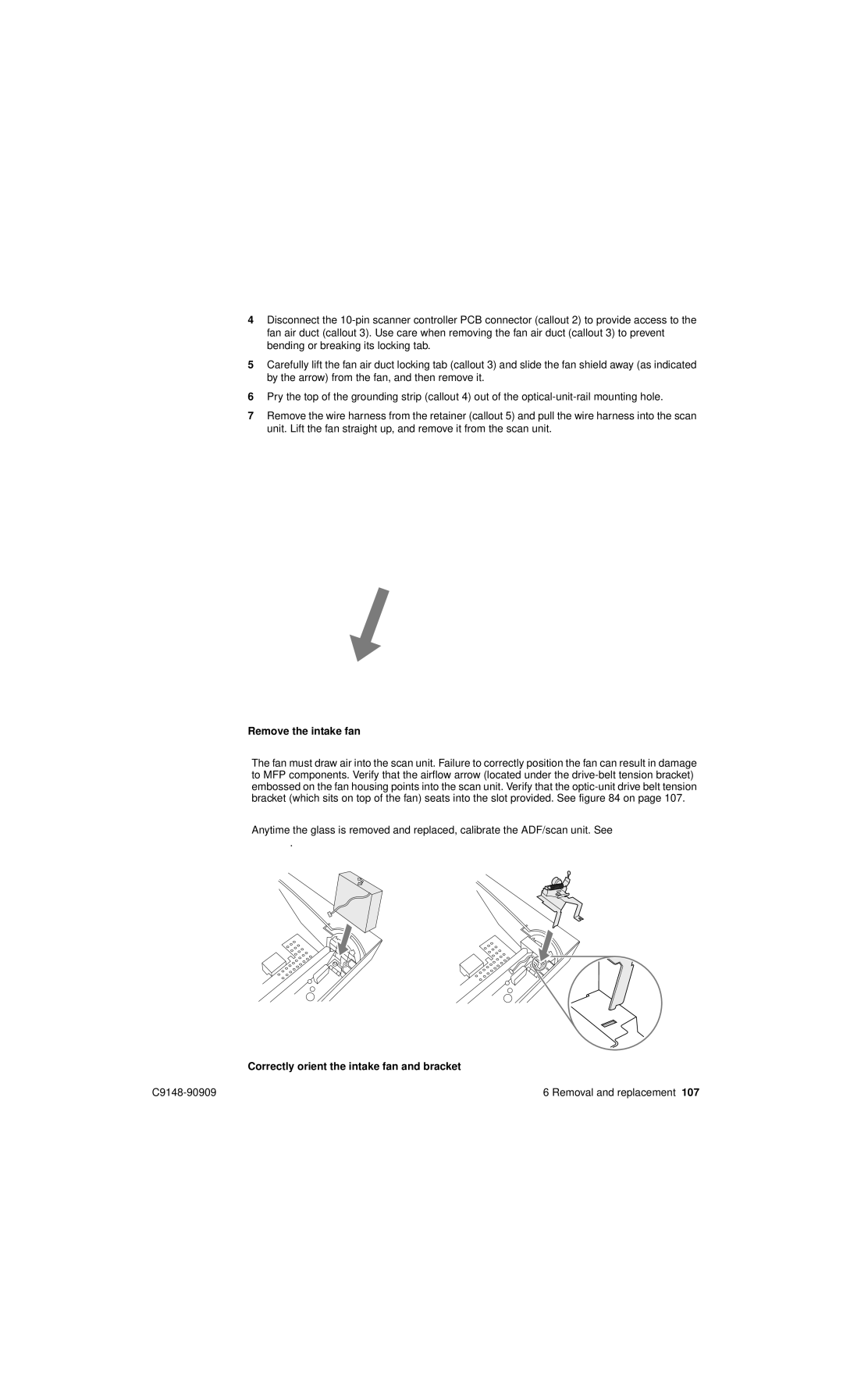
Figure 83. Remove the intake fan
CAUTIONThe fan must draw air into the scan unit. Failure to correctly position the fan can result in damage to MFP components. Verify that the airflow arrow (located under the
Reinstall Note Anytime the glass is removed and replaced, calibrate the ADF/scan unit. See “Calibration” on page 47.
Figure 84. Correctly orient the intake fan and bracket
6 Removal and replacement 107 |