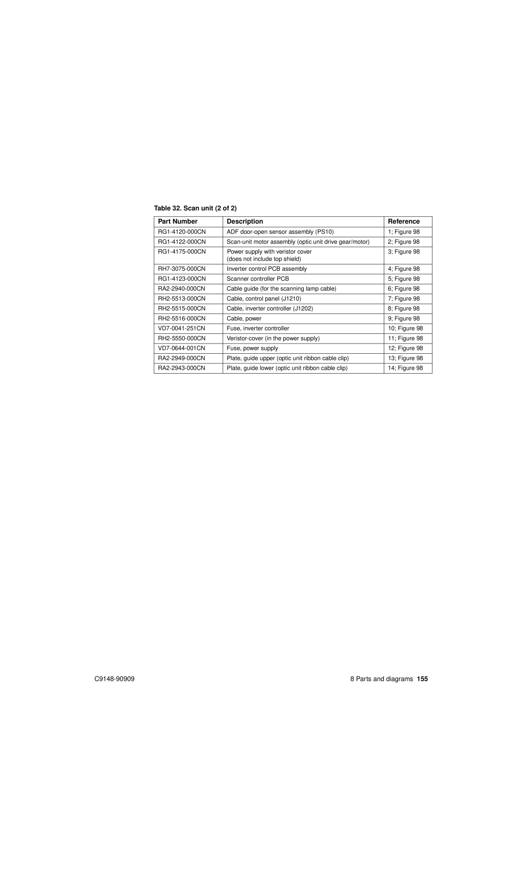
Table 32. Scan unit (2 of 2)
Part Number | Description | Reference |
|
|
|
ADF | 1; Figure 98 | |
|
|
|
2; Figure 98 | ||
|
|
|
Power supply with veristor cover | 3; Figure 98 | |
| (does not include top shield) |
|
|
|
|
Inverter control PCB assembly | 4; Figure 98 | |
|
|
|
Scanner controller PCB | 5; Figure 98 | |
|
|
|
Cable guide (for the scanning lamp cable) | 6; Figure 98 | |
|
|
|
Cable, control panel (J1210) | 7; Figure 98 | |
|
|
|
Cable, inverter controller (J1202) | 8; Figure 98 | |
|
|
|
Cable, power | 9; Figure 98 | |
|
|
|
Fuse, inverter controller | 10; Figure 98 | |
|
|
|
11; Figure 98 | ||
|
|
|
Fuse, power supply | 12; Figure 98 | |
|
|
|
Plate, guide upper (optic unit ribbon cable clip) | 13; Figure 98 | |
|
|
|
Plate, guide lower (optic unit ribbon cable clip) | 14; Figure 98 | |
|
|
|
8 Parts and diagrams 155 |