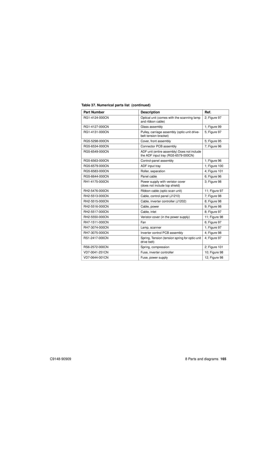
Table 37. Numerical parts list (continued)
Part Number | Description | Ref. |
|
|
|
Optical unit (comes with the scanning lamp | 2; Figure 97 | |
| and ribbon cable) |
|
|
|
|
Glass assembly | 1; Figure 99 | |
|
|
|
Pulley, carriage assembly | 5; Figure 97 | |
| belt tension bracket) |
|
|
|
|
Cover, front assembly | 5; Figure 95 | |
|
|
|
Connector PCB assembly | 7; Figure 96 | |
|
|
|
ADF unit (entire assembly) Does not include |
| |
| the ADF input tray |
|
|
|
|
1; Figure 96 | ||
|
|
|
ADF input tray | 1; Figure 100 | |
|
|
|
Roller, separation | 4; Figure 101 | |
|
|
|
Panel cable | 6; Figure 96 | |
|
|
|
Power supply with veristor cover | 3; Figure 98 | |
| (does not include top shield) |
|
|
|
|
Ribbon cable (optic scan unit) | 11; Figure 97 | |
|
|
|
Cable, control panel (J1210) | 7; Figure 98 | |
|
|
|
Cable, inverter controller (J1202) | 8; Figure 98 | |
|
|
|
Cable, power | 9; Figure 98 | |
|
|
|
Cable, inlet | 8; Figure 97 | |
|
|
|
11; Figure 98 | ||
|
|
|
Fan | 6; Figure 97 | |
|
|
|
Lamp, scanner | 1; Figure 97 | |
|
|
|
Inverter control PCB assembly | 4; Figure 98 | |
|
|
|
Spring, Tension (tension spring for | 4; Figure 97 | |
| drive belt) |
|
|
|
|
Spring, compression | 2; Figure 101 | |
|
|
|
Fuse, inverter controller | 10; Figure 98 | |
|
|
|
Fuse, power supply | 12; Figure 98 | |
|
|
|
8 Parts and diagrams 165 |