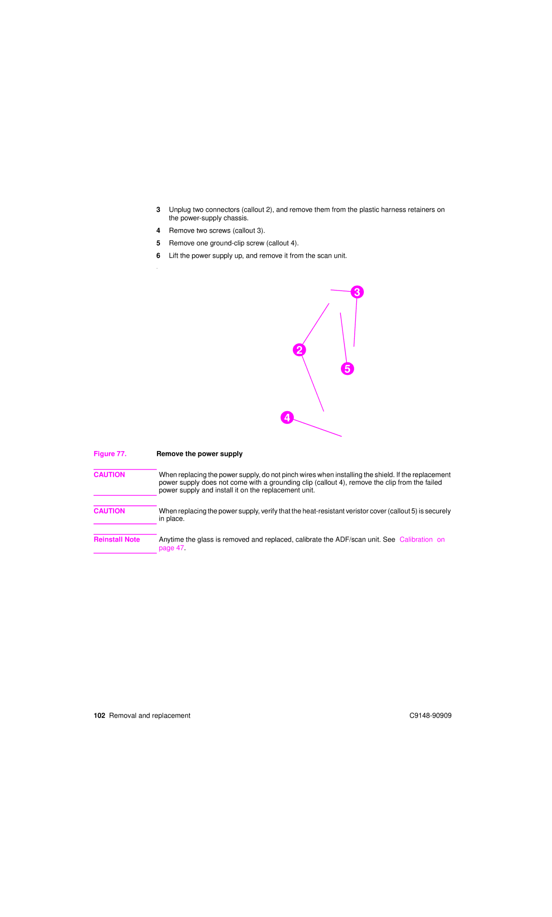
3Unplug two connectors (callout 2), and remove them from the plastic harness retainers on the
4Remove two screws (callout 3).
5Remove one
6Lift the power supply up, and remove it from the scan unit.
.
3
2
5
4
Figure 77. Remove the power supply
CAUTIONWhen replacing the power supply, do not pinch wires when installing the shield. If the replacement power supply does not come with a grounding clip (callout 4), remove the clip from the failed power supply and install it on the replacement unit.
CAUTION | When replacing the power supply, verify that the |
| in place. |
|
|
Reinstall Note Anytime the glass is removed and replaced, calibrate the ADF/scan unit. See “Calibration” on page 47.
102 Removal and replacement |