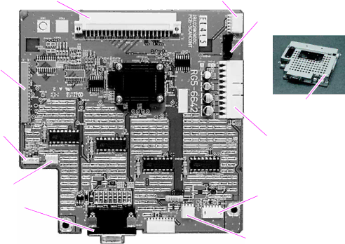
Scanner controller board connectors
J 1209 | J1210 |
PI1201
J1208
Scanner controller with the shield on
J1207 | J1201 |
J1206
J1202
J1205 ![]()
![]() J1203
J1203
Figure 23. Scanner controller board connectors (shield off)
Table 10. Scanner controller board connectors
Connector | Description | Remarks |
|
|
|
J1201 | ||
|
| remove the glass. See “Glass” on page 92. |
|
|
|
J1202 | Inverter PCB connector | |
|
| remove the glass. See “Glass” on page 92. |
|
|
|
J1203 | Flatbed intake fan | |
|
| remove the glass. See “Glass” on page 92. |
|
|
|
J1205 | ADF connector | |
|
| thumb screws are tight. This connector can be removed |
|
| accessed without removing any other MFP components. |
|
|
|
J1206 | ADF | |
|
| remove the glass. See “Glass” on page 92. |
|
|
|
J1207 | ||
|
| remove the glass. See “Glass” on page 92. |
|
|
|
J1208 | CCD connector | Flat ribbon cable. To gain access to this cable, remove |
|
| the glass. See “Glass” on page 92. |
|
|
|
J1209 | Intermediate PCB | This connector connects the copy processor board to the |
|
| scanner controller board. It cannot be disconnected |
|
| independently of removing the scanner controller board. |
|
|
|
J1210 | Control panel | |
|
| remove the glass. See “Glass” on page 92. |
|
|
|
PI1201 | This sensor is soldered to the scanner controller board. | |
|
| To gain access to this sensor, remove the glass. See |
|
| “Glass” on page 92. |
|
|
|
62 Theory of operation |
