Inverter PCB
1Remove the glass. See “Glass” on page 92.
CAUTION
The product contains components that are sensitive to electrostatic discharge (ESD). Always perform service work at an
Hint |
| The inverter PCB is | |
|
| fuse is not open. The inverter PCB will not function if the fuse is open. | |
|
|
|
|
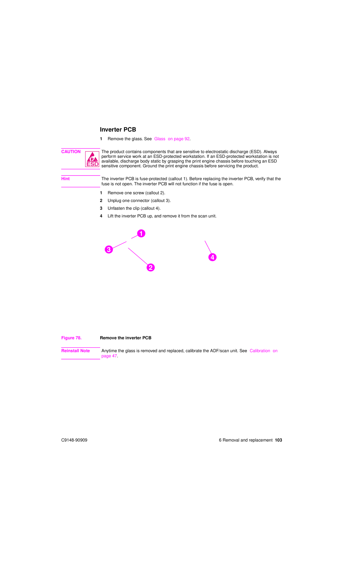
| 1 | Remove one screw (callout 2). | |
| 2 | Unplug one connector (callout 3). | |
| 3 | Unfasten the clip (callout 4). | |
| 4 | Lift the inverter PCB up, and remove it from the scan unit. | |
F1
32
43
12
Figure 78. Remove the inverter PCB
Reinstall Note Anytime the glass is removed and replaced, calibrate the ADF/scan unit. See “Calibration” on page 47.
6 Removal and replacement 103 |