3Center the optical unit in the scan unit to allow access to the
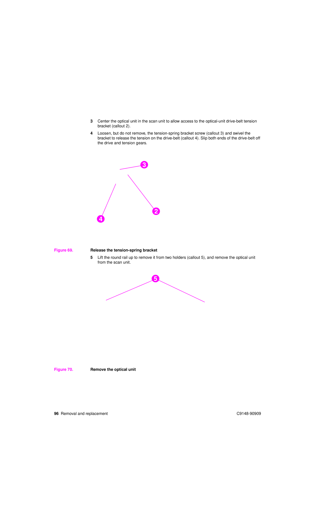
4Loosen, but do not remove, the
3
2
4
Figure 69. Release the tension-spring bracket
5Lift the round rail up to remove it from two holders (callout 5), and remove the optical unit from the scan unit.
5
Figure 70. Remove the optical unit
96 Removal and replacement |