SR5 0
Cause physical damage only
This section is specifically about safety matters
Conditions, resulting in death or severe injury
Page
Page
Page
How to Use the Input Signals
Multi-speed setting RL, RM, RH, REX signals Setting 0, 1, 2
Handling of the RS-485 Connector
Biases and gains of the frequency setting voltage current
Stall prevention
Frequency jump
Restart setting
Operation mode selection PID control 101
Monitoring reference
Retry function PWM carrier frequency Applied motor
To know the operating status at the occurrence of alarm
137
145
Correspondence between digital and actual characters 145
Wiring
Abbreviations
FR-S520-0.1K to 3.7K -R -C FR-S540-0.4K to 3.7K -R
Terminal connection diagram
Japanese Version
NFB MC
Layout and wiring of main circuit terminals
FR-S520S-0.1K to 1.5K -R -C FR-S510W-0.1K to 0.75K -R
FR-S520-0.1K to 3.7K-NA FR-S540-0.4K to 3.7K-NA R
North America Version
Inverter
FR-S510W-0.1K, 0.2K, 0.4K-NA FR-S510W-0.75K-NA
Reduce the output current
European Version
FR-S540-0.4K to 3.7K-ECR
FR-S520S-0.2K, 0.4K, 0.75K-EC R FR-S520S-1.5K-EC R
FR-S520S-0.2K to 1.5K-EC R
FR-S540-0.4K, 0.75K, 1.5K, 2.2K, 3.7K-EC R
Description of I/O Terminal Specifications
Main circuit
Control circuit
Terminal names in parentheses are those of the EC version
RUN
How to Use the Main Circuit Terminals
Cables, wiring lengths, crimping terminals, etc
FR-S520S-0.1K to 1.5K -R FR-S520S-0.2K to 1.5K-EC R
FR-S510W-0.1K to 0.75K -R FR-S510W-0.1K to 0.75K-NA
Wiring instructions
Peripheral devices
Selection of peripheral devices
Cables mm2
AC Reactor DC Reactor Model
L1, N
To-ground leakage currents
Line-to-line leakage currents
During commercial power
Type SP, CF, SF, CP
Rated sensitivity current
∆ n ≥ 10 ⋅ lg1+Ign+lg2+lgm
Power-off and magnetic contactor MC
Inverters primary side magnetic contactor MC
OFF
STF STR
Regarding noise and the installation of a noise filter
NFB FR-BAL
Grounding precautions
Noise reduction examples
BLF
BIF
Regarding power harmonics
Japanese power harmonic suppression guideline
Received Power Voltage 5th 7th 11th 13th 17th 19th 23rd Over
Conversion Factors for FR-S500 Series
Harmonic suppression technique requirement
Harmonic suppression techniques
Rated 6kV
No reactor, 100% operation ratio
M3 A, B, C terminals Al 0.5-6WH
How to Use the Control Circuit Terminals
Terminal block layout
Changing the control logic
Input signals are set to sink
Using tweezers, a pair of long
STR
RUN 24VDC
STR R
Run start and stop STF, STR, Stop
Right The forward/reverse rotation signal is
Input Terminals
Three-wire type connection STF, STR, Stop
STF-SD
STR-SD
Voltage input 10, 2
Basic
Manual-Automatic Switching
External frequency selection REX, RH, RM, RL
Current input 4, 5, AU
AU-SD on OFF
External command
REX
Indicator connection and adjustment
Japanese version FM
Output waveform of terminal FM
NA and EC version AM
CPU
Signal inputs by contactless switches
Control circuit common terminals SD, 5, SE
Start self-holding selection Stop signal Setting
Second function selection RT signal Setting
Current input selection AU signal Setting
Output shut-off MRS signal Setting
External thermal relay input Setting
Jog operation using external signals
Jog operation JOG signal Setting
Reset signal Setting
PID control valid terminal Setting
PU operation/external operation switching Setting
When connecting the parameter unit
Use the optional FR-CB2
4P Twisted pair cable, 4 pairs
System configuration examples
RS-485 communication
Wiring methods
Wiring of one RS-485 computer and one inverter
Design Information
MC1
Functions
Communication Parameters Only for the Type
Function Parameter List
Minimum Factory Cus Name Setting Range
Func- Pa- Indica- tion rame- tion ter
Minimum Factory Refer Cus Name Setting Range
FM AM
PWM
THM, THT, GF
OHT, OLT, PE, OPT
Selection functions
PID
Alarm history 115 Clear
ECL
NA, EC
Func Tion
Cation
For details of the program, refer to page 118 onwards
Com Minimum
List of Parameters Classified by Purpose of Use
Related to monitoring
Setting
Name Factory Setting Remarks
Explanation of Functions Parameters
Torque boost
Base frequency, Base frequency voltage
Parameter Name Factory Setting Setting Range EC version
Maximum and minimum frequency
EC version
Multi-speed operation to to
Remarks Range
Acceleration/deceleration time
Frequency setting Hz 120 Acceleration Deceleration time s
Operation, etc. or the timing of operating
Electronic overcurrent protection
DC injection brake
Starting frequency
Name Factory
Load pattern selection
Name Factory Setting Setting Range Remarks
Jog frequency
RUN key rotation direction selection
Refer to Refer to ,
Stall Prevention OL Signal Operation Fast Output
Stall prevention function and current limit function
CelerationDe Operation Activated
Deceleration Operation Not Activated Regenerative Driving
Stall prevention
100
Where, a =
Function Description
Acceleration/deceleration pattern
Set the acceleration/deceleration pattern
Extended function display selection
Frequency jump
Speed display
Biases and gains of the frequency setting voltage current
Setting
Name Factory Setting
Use Pr , calibration parameter C4 for
How to change the highest frequency
Flicker ... Parameter setting complete
OperationDisplay
Set value Hz
Voltage gain appears Press the SET key to show the analog
Press the SET key to set the value
Key twice to show the next parameter
Turn the setting dial to read another parameter
Key to return to
Up-to-frequency sensitivity
Start-time ground fault detection selection
Output Terminal Function Parameters
Output frequency detection
Parameter Name Factory Setting Remarks Range
Current Detection Function Parameters
Output current detection functions
On OFF
Zero current detection
LED
Display Function Parameters
Monitor display
Refer to
Setting dial function selection
Press the RUN key to start the inverter
Restart setting
Restart Operation Parameters
Monitoring reference
Maximum output voltage of terminal AM is 5VDC
Setting Description
Refer to the following table and set the parameters
Automatic restart operation after
Stfstr
Remote setting function selection
Or PU digital preset frequency
Operation panel operation procedure
Additional Function Parameters
Function E 2PROM
Frequency setting storage conditions
Pr Setting
Terminal Function Selection Parameters
Input terminal function selection
Setting Signal Functions Related Parameters Name
MRS
REX
JOG
Setting Signal Function Operation Parameters
Output terminal function selection
Same function may be set to more than one terminal
Referred to
Pr Setting Number of Retries Alarm Signal Output
Operation Selection Function Parameters
Retry function
Protective Functions Major Failures for Retries
You can change the motor sound
Parameter Number Setting Description
PWM carrier frequency
Applied motor
Voltage input selection
Set the motor used
Acceleration/deceleration time, which is a slope up/down to
Reset selection/PU stop selection
Parameter Name Factory Setting Setting Range Remarks
Setting Remarks
Reset Selection PU Stop Selection Setting
Key input from
Operation panel Restarting method with Shown
Cooling fan operation selection
Pr Setting Function
Parameter write inhibit selection
Operation mode selection
Reverse rotation prevention selection
Mode Signal
Function LED Indication * PU
EXT
RUN EXT
PU operation interlock
MRS
PID control to
Operation mode switching by external signal
X16 Signal Operation Mode
102
Setting Basic PID control configuration
PID action overview
PID action
Reverse action
Increases the manipulated
Variable output frequency if Deviation X = set point
Wiring example
Deviation
Negative
RUNFUP,FDN
O signals
Parameter setting
Name Setting Description
105
Adjustment procedure
106
Calibration example
107
Start
END
108
Set point input calibration
Detector output calibration
Auxiliary Function Parameters
Slip compensation
11.2
Automatic torque boost selection
Ordinary V/F control and torque boost Pr , Pr are valid
Operating conditions
110
Parameter Name Factory Setting Remarks
Calibration Parameters
Motor primary resistance
Meter frequency meter calibration Japanese version
Flicker ... Parameter setting complete
112
Meter frequency meter calibration NA and EC version
Display
When the FR-PU04 is used, make calibration with Pr 114
Operation
Alarm history clear
Erases the alarm history
Clear Parameters
Parameter clear
Symbol Switching Type
Operational functions
Operation mode-based functions
Communication settings
14.1
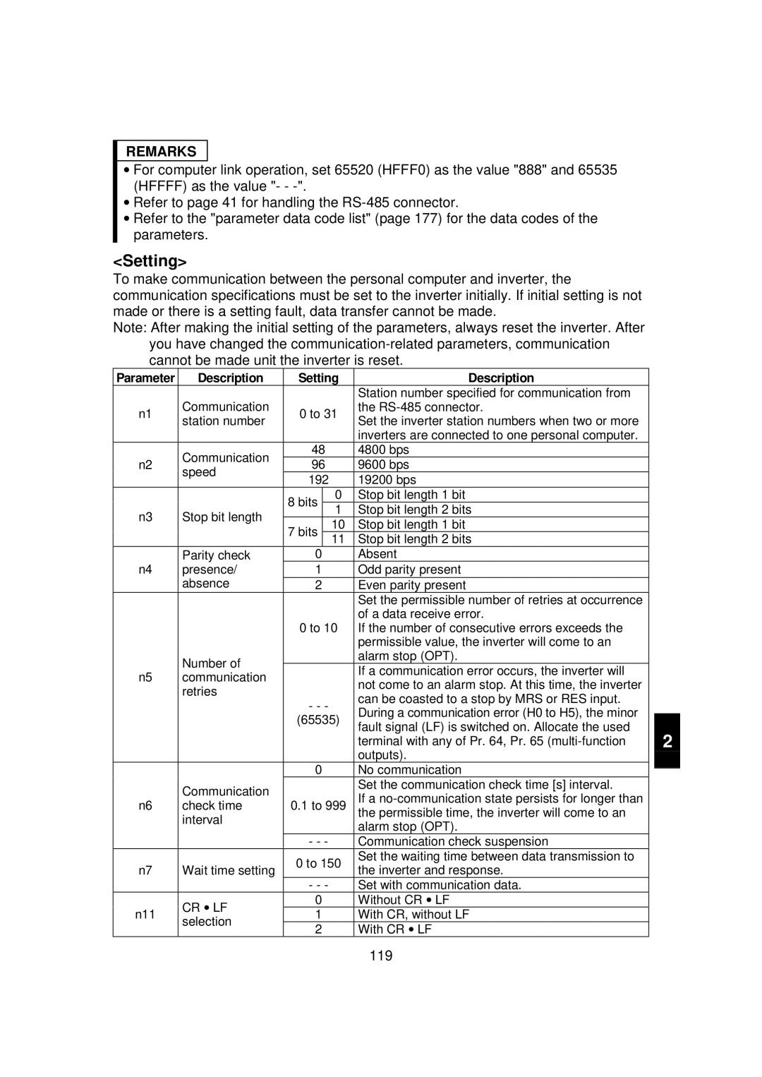
Communication-related parameters
118
CR LF
Description Setting
119
Inverter Monitor Parame
Computer programming Communication protocol
Operation Run Running
Data format
Reply data from inverter to computer during data write
Reply data from inverter to computer during data read
121
Signal Ascii Code Description
Data definitions
Send data from computer to inverter during data read
Control codes
123
STX ACK ENQ
124
Instruction Data
H7F
HFF
Page
FF =
Setting items and set data
126
127
Calibra
HEC
Nication Tion
Error Code List
Error Definition
128
Description Data
Operation at alarm occurrence
Communication error
General flowchart
Program example
N9 Pr Speed Command write
Operation and speed command write
Location Selection N8 Pr Operation Command write
Link start mode selection
N8 Pr operation Command write
N10 Link start mode Setting is enabled when Pr = Selection
Explanation of table External
14.4 E2PROM write selection
Parameter Unit FR-PU04 Setting
Parameter unit display language switching
N13 Setting Display Language
15.2
PU contrast adjustment
N15 PU contrast adjustment Setting is enabled when Pr =
PU main display screen data selection
N16 100
N17 Setting PU Disconnection Detection PU Setting Lock
PU disconnection detection/PU setting lock
Monitor display and Resetstop key are valid
Functions
136
Errors Alarms
Error alarm definitions
Major failures
OC1 FR-PU04
138
OC2 FR-PU04
OC3 FR-PU04
OV1 FR-PU04
139
OV3
THM
THT
140
OHT FR-PU04
OLT FR-PU04
OPT FR-PU04
Minor failures
For only the type having the RS-485 communication function
141
PUE
142
143
Write errors
Er1 FR-PU04 Control Mode
Er2 FR-PU04 PU/EXT Mode
144
Operator ERR
Er3 FR-PU04 Incr I/P
Actual Display
Resetting the inverter
Correspondence between digital and actual characters
Troubleshooting
Motor remains stopped
Speed greatly differs from the setting
Motor rotates in opposite direction
Acceleration/deceleration is not smooth
Motor current is large
Operation mode is not changed properly
Operation panel display is not operating
Parameter write cannot be performed
Motor produces annoying sound
Precautions for Maintenance and Inspection
Precautions for maintenance and inspection
Check items
Periodic inspection
Insulation resistance test using megger
Pressure test
Daily and periodic inspection
Interval Daily
151
Inspection Description
Interval
Daily 1 year
Inspection Interval
Module device numbers and terminals to be checked
Checking the inverter and converter modules Preparation
Checking method
Replacement of parts
Part Name Standard Replacement Interval Description
Cooling fan
Inverter Model No Fan Type
AIR Flow
Smoothing capacitors
Relays
Measurement of main circuit voltages, currents and powers
Typical Measuring Points and Instruments
Pf1=
Pf2=
158
Measuring Point Remarks Instrument Reference Measured Value
Measuring Point
RH, RM, RL, MRS
RES-SD
Measuring Remarks Instrument
Cations
160
Ratings
Specification List
Phase 200V power supply
Phase 400V power supply
Single-phase 200V power supply
Single-phase 100V power supply
Common specifications
NA, EC
Outline Drawings
168
Panel cut dimension drawing
Parameter unit FR-PU04 Outline drawing
Instructions
170
Selecting Instructions
Peripheral Selecting Instructions
Installation of thermal relay
Disuse of power factor improving capacitor power capacitor
Handling of primary side magnetic contactor
Handling of secondary side magnetic contactor
Cable thickness and wiring distance
Wiring
Operating Instructions
Operation
Installation
Power supply
Suppressing the surge voltage on the inverter side
Inverter-driven 400V class motor
Rectifying the motor insulation
Appendix
176
Func- Parameter tion Number
Data Code Computer
Extension
Link Data
Read
178
Data Code Computer Link Parameter Extension
179
180
Link Parameter Extension Setting Data Code 7F/FF
181
Data Code Computer Func
Name Link Data Tion
Manual number is given on the bottom left of the back cover
Print Date Manual Number Revision