X20 Sprayer Reference Manual
3-Wire Section Valves
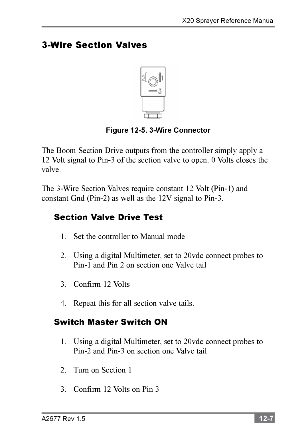
Figure 12-5. 3-Wire Connector
The Boom Section Drive outputs from the controller simply apply a 12 Volt signal to
The
Section Valve Drive Test
1.Set the controller to Manual mode
2.Using a digital Multimeter, set to 20vdc connect probes to
3.Confirm 12 Volts
4.Repeat this for all section valve tails.
Switch Master Switch ON
1.Using a digital Multimeter, set to 20vdc connect probes to
2.Turn on Section 1
3.Confirm 12 Volts on Pin 3
A2677 Rev 1.5 |
