AM/FM Scaling
The magnitude of the AM/FM output signal at
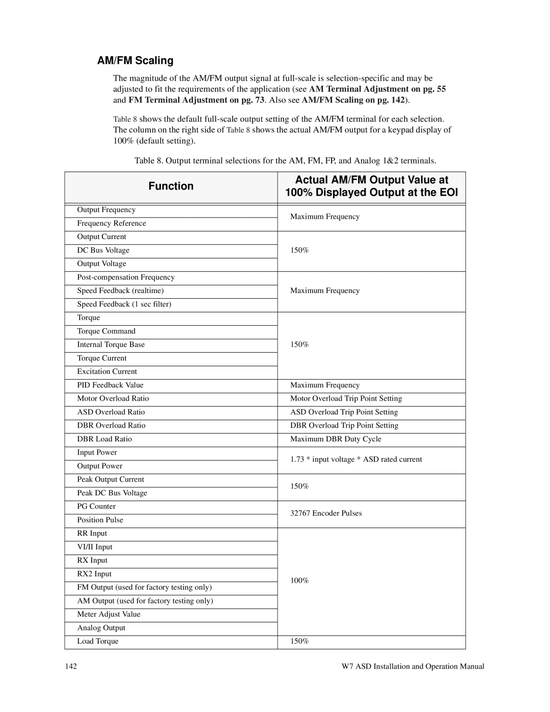
Table 8 shows the default
Table 8. Output terminal selections for the AM, FM, FP, and Analog 1&2 terminals.
Function | Actual AM/FM Output Value at | |
100% Displayed Output at the EOI | ||
| ||
|
| |
|
| |
Output Frequency | Maximum Frequency | |
| ||
Frequency Reference | ||
| ||
|
| |
Output Current |
| |
|
| |
DC Bus Voltage | 150% | |
|
| |
Output Voltage |
| |
|
| |
| ||
|
| |
Speed Feedback (realtime) | Maximum Frequency | |
|
| |
Speed Feedback (1 sec filter) |
| |
|
| |
Torque |
| |
|
| |
Torque Command |
| |
|
| |
Internal Torque Base | 150% | |
|
| |
Torque Current |
| |
|
| |
Excitation Current |
| |
|
| |
PID Feedback Value | Maximum Frequency | |
|
| |
Motor Overload Ratio | Motor Overload Trip Point Setting | |
|
| |
ASD Overload Ratio | ASD Overload Trip Point Setting | |
|
| |
DBR Overload Ratio | DBR Overload Trip Point Setting | |
|
| |
DBR Load Ratio | Maximum DBR Duty Cycle | |
|
| |
Input Power | 1.73 * input voltage * ASD rated current | |
| ||
Output Power | ||
| ||
|
| |
Peak Output Current | 150% | |
| ||
Peak DC Bus Voltage | ||
| ||
|
| |
PG Counter | 32767 Encoder Pulses | |
| ||
Position Pulse | ||
| ||
|
| |
RR Input |
| |
|
| |
VI/II Input |
| |
|
| |
RX Input |
| |
|
| |
RX2 Input | 100% | |
| ||
FM Output (used for factory testing only) | ||
| ||
|
| |
AM Output (used for factory testing only) |
| |
|
| |
Meter Adjust Value |
| |
|
| |
Analog Output |
| |
|
| |
Load Torque | 150% | |
|
|
142 | W7 ASD Installation and Operation Manual |