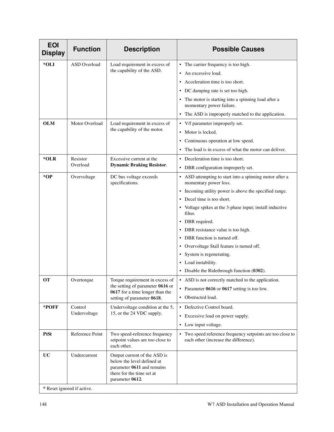
EOI | Function | Description |
| Possible Causes |
Display |
| |||
|
|
|
| |
|
|
|
|
|
*OLI | ASD Overload | Load requirement in excess of | • | The carrier frequency is too high. |
|
| the capability of the ASD. | • | An excessive load. |
|
|
| ||
|
|
| • Acceleration time is too short. | |
|
|
| • DC damping rate is set too high. | |
|
|
| • The motor is starting into a spinning load after a | |
|
|
|
| momentary power failure. |
|
|
| • The ASD is improperly matched to the application. | |
|
|
|
|
|
OLM | Motor Overload | Load requirement in excess of | • | V/f parameter improperly set. |
|
| the capability of the motor. | • | Motor is locked. |
|
|
| ||
|
|
| • Continuous operation at low speed. | |
|
|
| • The load is in excess of what the motor can deliver. | |
|
|
|
|
|
*OLR | Resistor | Excessive current at the | • | Deceleration time is too short. |
| Overload | Dynamic Braking Resistor. | • DBR configuration improperly set. | |
|
|
| ||
|
|
|
|
|
*OP | Overvoltage | DC bus voltage exceeds | • | ASD attempting to start into a spinning motor after a |
|
| specifications. |
| momentary power loss. |
|
|
| • Incoming utility power is above the specified range. | |
|
|
| • Decel time is too short. | |
|
|
| • Voltage spikes at the | |
|
|
|
| filter. |
|
|
| • | DBR required. |
|
|
| • DBR resistance value is too high. | |
|
|
| • DBR function is turned off. | |
|
|
| • Overvoltage Stall feature is turned off. | |
|
|
| • | System is regenerating. |
|
|
| • | Load instability. |
|
|
| • Disable the Ridethrough function (0302). | |
|
|
|
|
|
OT | Overtorque | Torque requirement in excess of | • | ASD is not correctly matched to the application. |
|
| the setting of parameter 0616 or | • Parameter 0616 or 0617 setting is too low. | |
|
| 0617 for a time longer than the | ||
|
|
|
| |
|
| setting of parameter 0618. | • | Obstructed load. |
|
|
|
|
|
*POFF | Control | Undervoltage condition at the 5, | • | Defective Control board. |
| Undervoltage | 15, or the 24 VDC supply. | • Excessive load on power supply. | |
|
|
| ||
|
|
| • | Low input voltage. |
|
|
|
|
|
PtSt | Reference Point | Two | • | Two speed reference frequency setpoints are too close to |
|
| setpoint values are too close to |
| each other (increase the difference). |
|
| each other. |
|
|
|
|
|
|
|
UC | Undercurrent | Output current of the ASD is |
|
|
|
| below the level defined at |
|
|
|
| parameter 0611 and remains |
|
|
|
| there for the time set at |
|
|
|
| parameter 0612. |
|
|
|
|
|
|
|
* Reset ignored if active. |
|
|
| |
|
|
|
|
|
148 | W7 ASD Installation and Operation Manual |