Vector Motor Model Slip Frequency Gain |
| VI/II Speed Frequency Setpoint #1 | |||||
|
|
| |||||
Vector Motor Model Slip Frequency Gain |
|
| |||||
Program |
| Motor Settings Vector Motor Model Slip Frequency | Parameter Type — Numerical | ||||
Gain |
|
|
|
| Factory Default — 0.60 | ||
|
|
|
|
|
| ||
This parameter provides a degree of slip compensation for a given load. A | Changeable During Run — Yes | ||||||
higher setting here decreases the slip allowed for a given load/ASD output ratio. | |||||||
| |||||||
|
|
|
|
|
| Minimum — 0.00 | |
|
|
|
|
|
| Maximum — 2.55 | |
|
|
|
| ||||
V/f Pattern |
|
|
| ||||
Program |
| Fundamental Parameters Fundamental #1 | V/f Pattern | Parameter Type — Selection List | |||
This function establishes the relationship between the output frequency and the | Factory Default — Variable Torque | ||||||
output voltage. |
|
| |||||
|
| Changeable During Run — No | |||||
Settings: |
|
|
|
| |||
|
|
|
|
| |||
| Constant Torque |
|
|
| |||
| Variable Torque |
|
|
| |||
|
|
| |||||
VI/II Speed Frequency Setpoint #1 |
|
| |||||
Program |
| Frequency Settings Speed Reference Setpoints VI/II | Parameter Type — Numerical | ||||
| VI/II Speed Frequency Setpoint #1 |
| Factory Default — 0.0 | ||||
This parameter⇒⇒is used to set the gain and bias of the VI/II input terminal when | |||||||
Changeable During Run — Yes | |||||||
the VI/II terminal is used as the control input while operating in the Speed | |||||||
| |||||||
Control mode. |
|
| Minimum — 0.0 | ||||
| Note: See note on pg. 33 for further information on the VI/II |
| Maximum — Max. Freq. | ||||
|
| terminal. |
|
| Units — Hz | ||
|
|
|
|
|
| ||
VI/II Input Speed Control Setup |
|
|
| ||||
Perform the following setup to allow the system to receive Speed control input |
| ||||||
at the VI/II input terminal: | ⇒ | ⇒ |
| ||||
|
| ⇒ |
|
| |||
• | Program | Utilities Command and Frequency Settings | Command |
| |||
| Mode Select Terminal Block. |
|
|
| |||
• | Program ⇒Utilities ⇒Command and Frequency Settings ⇒Frequency#1 |
| |||||
| Mode Select ⇒VI/II. |
|
|
| |||
• | Provide a Run command (F and/or R). |
|
|
| |||
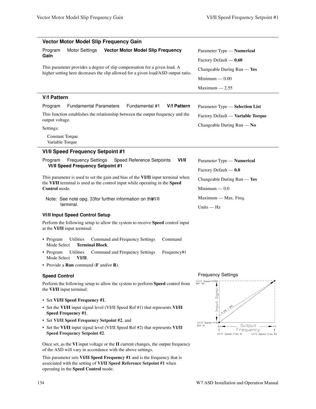
Speed Control | Frequency Settings |
Perform the⇒following setup to allow⇒the system to perform Speed control⇒from |
|
the⇒VI/II input terminal: |
|
•Set VI/II Speed Frequency #1,
•Set the VI/II input signal level (VI/II Speed Ref #1) that represents VI/II Speed Frequency #1,
• Set VI/II Speed Frequency Setpoint #2, and
• Set the VI/II input signal level (VI/II Speed Ref #2) that represents VI/II Speed Frequency Setpoint #2.
Once set, as the VI input voltage or the II current changes, the output frequency of the ASD will vary in accordance with the above settings.
This parameter sets VI/II Speed Frequency #1 and is the frequency that is associated with the setting of VI/II Speed Reference Setpoint #1 when operating in the Speed Control mode.
134 | W7 ASD Installation and Operation Manual |