FL Terminal |
|
|
|
|
|
| FM Terminal Adjustment | ||
FL Terminal |
|
|
|
|
|
| |||
Program |
| Terminal Settings | Output Terminals | FL Terminal | Parameter Type — Selection List | ||||
Assignment |
|
|
|
|
| Factory Default — Fault (All) | |||
|
|
|
|
|
|
|
| ||
This parameter sets the functionality of the FL output terminals to 1 of the 58 | Changeable During Run — No | ||||||||
possible functions that are listed in Table 7 on page 141. | |||||||||
| |||||||||
The on and off delay times of the FL terminals may be adjusted to provide |
| ||||||||
more response time to the device that is connected to the output terminals. |
| ||||||||
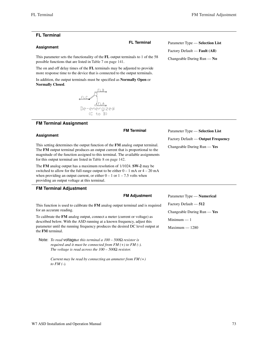
In addition, the output terminals must be specified as Normally Open or |
| ||||||||
Normally Closed. |
|
|
|
|
| ||||
FM Terminal Assignment |
|
|
|
|
| ||||
Program | ⇒ | Terminal Settings | AM/FM |
| FM | FM Terminal | Parameter Type — Selection List | ||
|
|
| ⇒⇒⇒ |
|
| ||||
Assignment |
|
|
|
|
| Factory Default — Output Frequency | |||
This setting determines the output function of the FM analog output terminal. |
| ||||||||
The FM output⇒ | terminal produces⇒an output current that⇒is proportional to the | Changeable During Run — Yes | |||||||
magnitude of the function assigned to this terminal. The available assignments |
| ||||||||
for this output terminal are listed in Table 8 on page 142. |
| ||||||||
The FM analog output has a maximum resolution of 1/1024. |
| ||||||||
switched to allow for the |
| ||||||||
when providing an output current, or either 0 – 1 or 1 – 7.5 volts when |
| ||||||||
providing an output voltage at this terminal. |
|
|
|
| |||||
FM Terminal Adjustment |
|
|
|
|
| ||||
Program |
| Terminal Settings | AM/FM |
| FM | FM Adjustment | Parameter Type — Numerical | ||
This function is used to calibrate the FM analog output terminal and is required | Factory Default — 512 | ||||||||
| |||||||||
for an accurate reading. |
|
|
|
| Changeable During Run — Yes | ||||
|
|
|
|
|
|
|
| ||
To calibrate the FM analog output, connect a meter (current or voltage) as | Minimum — 1 | ||||||||
described below. With the ASD running at a known frequency, adjust this | |||||||||
| |||||||||
parameter until the running frequency produces the desired DC level output at | Maximum — 1280 | ||||||||
the FM terminal. |
|
|
|
| |||||
|
|
|
|
| |||||
Note: To read voltage at this terminal a 100 – 500Ω resistor is |
| ||||||||
required and it must be connected from FM (+) to FM |
| ||||||||
The voltage is read across the 100 – 500Ω resistor. |
| ||||||||
Current may be read by connecting an ammeter from FM (+) |
| ||||||||
to⇒FM | ⇒ | ⇒ | ⇒ |
|
| ||||
W7 ASD Installation and Operation Manual | 73 |