Switching Network
System 25 uses distributed processing techniques to provide switched voice and data services. The switch operates at 64 Kbps. The switching network consists of the following:
●Time Division Multiplex (TDM) bus
●Port Circuits
●System Resource Circuits.
The TDM bus connects the intelligent ports to the Common Control circuit packs and other ports through the network control circuit. The system resource circuits provide tone sources, receivers, detectors, a n d p o o l e d m o d e m s . T h e i n t e l l i g e n t p o r t s c o n n e c t e x t e r n a l communications facilities to the TDM bus.
TDM BUS
The TDM bus consists of two groups of eight signal leads and five control leads, each with matching grounds. The port circuit packs place digitized voice [pulse code modulated (PCM)] signals on the bus.
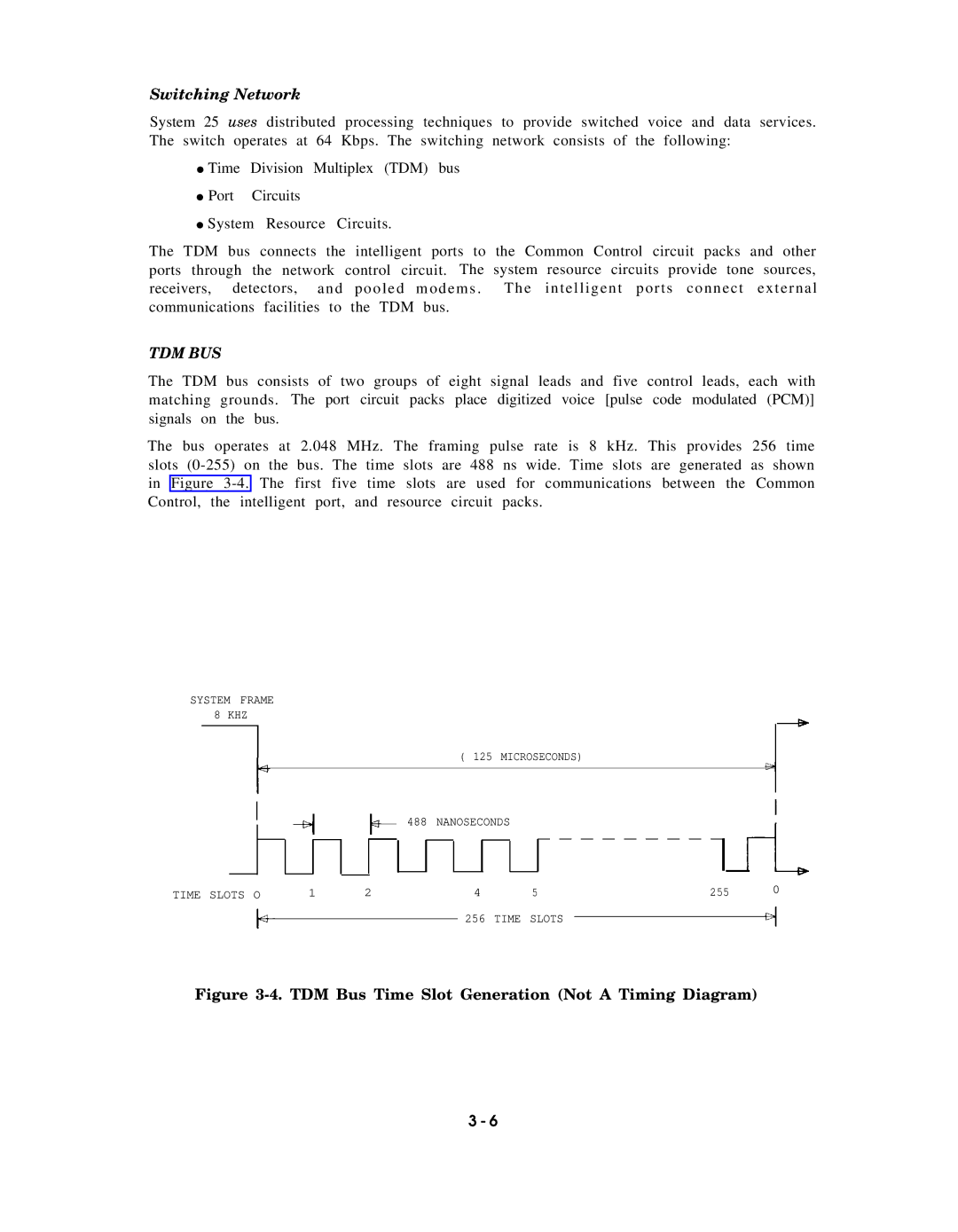
The bus operates at 2.048 MHz. The framing pulse rate is 8 kHz. This provides 256 time slots
SYSTEM FRAME
8 KHZ
|
|
|
|
|
|
|
|
|
|
| ( 125 | MICROSECONDS) |
|
|
|
|
| ||||||
|
|
|
|
|
|
|
|
|
|
|
|
|
|
|
|
|
|
|
|
|
|
| |
|
|
|
|
|
|
|
|
|
| 488 | NANOSECONDS |
|
|
|
|
| |||||||
|
|
|
|
|
|
|
|
|
|
|
|
|
|
| |||||||||
|
|
|
|
|
|
|
|
|
|
|
|
|
|
| |||||||||
|
|
|
|
|
|
|
|
|
|
|
|
|
|
| |||||||||
|
|
|
|
|
|
|
|
|
|
|
|
| |||||||||||
|
|
|
|
|
|
|
|
|
|
|
|
|
|
|
|
| — — — — — — — — — |
|
|
| 0 | ||
|
|
|
|
|
|
|
|
|
|
|
|
|
|
|
|
|
| ||||||
|
|
|
|
|
|
|
|
|
|
|
|
|
|
|
|
|
|
|
|
| |||
TIME SLOTS O | 1 | 2 |
|
|
| 4 |
| 5 |
|
| 255 |
| |||||||||||
|
|
|
|
|
|
|
|
|
|
|
| 256 | TIME SLOTS |
|
|
|
|
|
| ||||
|
|
|
|
|
|
|
|
|
|
|
|
|
|
|
|
| |||||||
|
|
|
|
|
|
|
|
|
|
|
|
|
|
|
|
|
| ||||||
Figure 3-4. TDM Bus Time Slot Generation (Not A Timing Diagram)
3 - 6