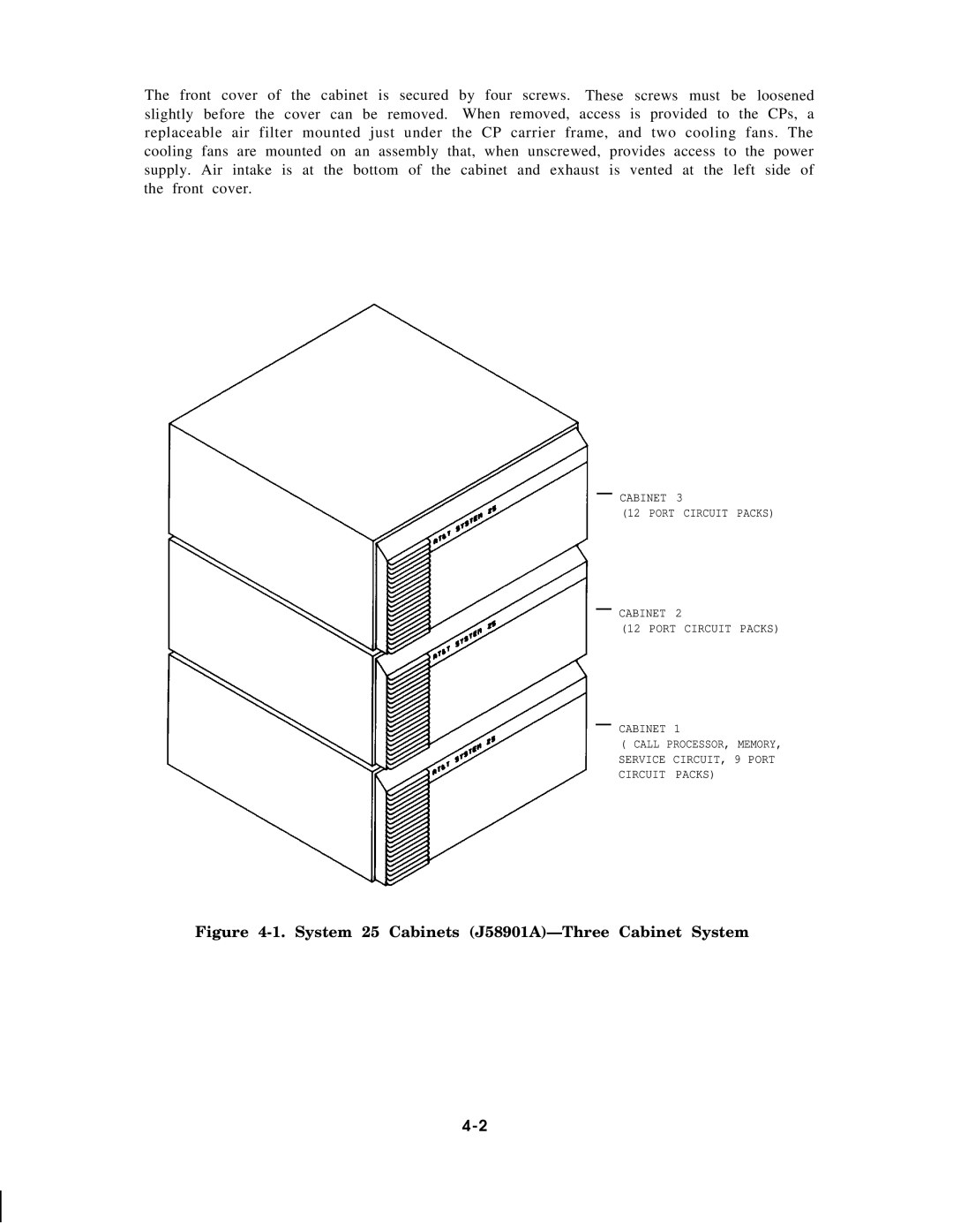
The front cover of the cabinet is secured by four screws. These screws must be loosened slightly before the cover can be removed. When removed, access is provided to the CPs, a replaceable air filter mounted just under the CP carrier frame, and two cooling fans. The cooling fans are mounted on an assembly that, when unscrewed, provides access to the power supply. Air intake is at the bottom of the cabinet and exhaust is vented at the left side of the front cover.
— CABINET 3
(12 PORT CIRCUIT PACKS)
— CABINET 2
(12 PORT CIRCUIT PACKS)
— CABINET 1
( CALL PROCESSOR, MEMORY, SERVICE CIRCUIT, 9 PORT CIRCUIT PACKS)
