60Cyclades® ACS 5000 Installation/Administration/User Guide
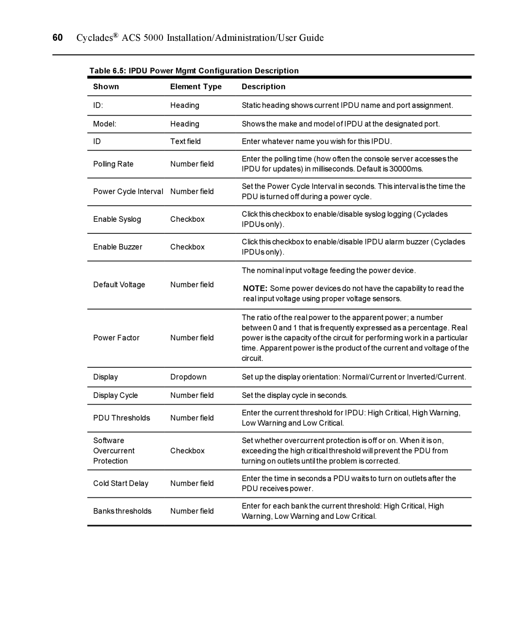
Table 6.5: IPDU Power Mgmt Configuration Description
Shown | Element Type | Description | |
ID: | Heading | Static heading shows current IPDU name and port assignment. | |
Model: | Heading | Shows the make and model of IPDU at the designated port. | |
ID | Text field | Enter whatever name you wish for this IPDU. | |
Polling Rate | Number field | Enter the polling time (how often the console server accesses the | |
IPDU for updates) in milliseconds. Default is 30000ms. | |||
|
| ||
Power Cycle Interval | Number field | Set the Power Cycle Interval in seconds. This interval is the time the | |
PDU is turned off during a power cycle. | |||
|
| ||
Enable Syslog | Checkbox | Click this checkbox to enable/disable syslog logging (Cyclades | |
IPDUs only). | |||
|
| ||
Enable Buzzer | Checkbox | Click this checkbox to enable/disable IPDU alarm buzzer (Cyclades | |
IPDUs only). | |||
|
| ||
|
| The nominal input voltage feeding the power device. | |
Default Voltage | Number field | NOTE: Some power devices do not have the capability to read the | |
|
| ||
|
| real input voltage using proper voltage sensors. | |
|
| The ratio of the real power to the apparent power; a number | |
|
| between 0 and 1 that is frequently expressed as a percentage. Real | |
Power Factor | Number field | power is the capacity of the circuit for performing work in a particular | |
|
| time. Apparent power is the product of the current and voltage of the | |
|
| circuit. | |
Display | Dropdown | Set up the display orientation: Normal/Current or Inverted/Current. | |
Display Cycle | Number field | Set the display cycle in seconds. | |
PDU Thresholds | Number field | Enter the current threshold for IPDU: High Critical, High Warning, | |
Low Warning and Low Critical. | |||
|
| ||
Software |
| Set whether overcurrent protection is off or on. When it is on, | |
Overcurrent | Checkbox | exceeding the high critical threshold will prevent the PDU from | |
Protection |
| turning on outlets until the problem is corrected. | |
Cold Start Delay | Number field | Enter the time in seconds a PDU waits to turn on outlets after the | |
PDU receives power. | |||
|
| ||
Banks thresholds | Number field | Enter for each bank the current threshold: High Critical, High | |
Warning, Low Warning and Low Critical. | |||
|
|