Functional Description
R
5.2System Memory Interface
The 845 chipset can be configured to support PC133 SDRAM.
5.2.1Single Data Rate (SDR) SDRAM Interface Overview
The MCH integrates a system memory SDRAM controller with a
The MCH includes support for:
•Up to 3 GB of 133 MHz SDR SDRAM
•PC133 unbuffered 168 pin SDR SDRAM DIMMs
•Maximum of 3 DIMMs,
•Configurable optional ECC
The two
The MCH’s system memory controller targets CAS latencies of 2 and 3 clocks for SDRAM. The MCH provides refresh functionality with a programmable rate (normal SDRAM rate is
1 refresh/15.6 us).
5.2.2Memory Organization and Configuration
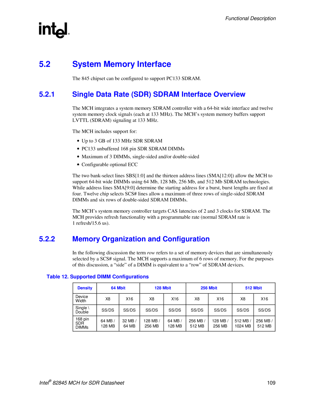
In the following discussion the term row refers to a set of memory devices that are simultaneously selected by a SCS# signal. The MCH supports a maximum of 6 rows of memory. For the purposes of this discussion, a “side” of a DIMM is equivalent to a “row” of SDRAM devices.
Table 12. Supported DIMM Configurations
Density | 64 Mbit | 128 Mbit | 256 Mbit | 512 Mbit | |||||
|
|
|
|
|
|
|
|
| |
Device | X8 | X16 | X8 | X16 | X8 | X16 | X8 | X16 | |
Width | |||||||||
|
|
|
|
|
|
|
| ||
Single \ | SS/DS | SS/DS | SS/DS | SS/DS | SS/DS | SS/DS | SS/DS | SS/DS | |
Double | |||||||||
|
|
|
|
|
|
|
| ||
168 pin | 64 MB / | 32 MB / | 128 MB / | 64 MB / | 256 MB / | 128 MB / | 512 MB / | 256 MB / | |
SDR | |||||||||
128 MB | 64 MB | 256 MB | 128 MB | 512 MB | 256 MB | 1024 MB | 512 MB | ||
DIMMs | |||||||||
|
|
|
|
|
|
|
|
| |
Intel® 82845 MCH for SDR Datasheet | 109 |
