Register Description
R
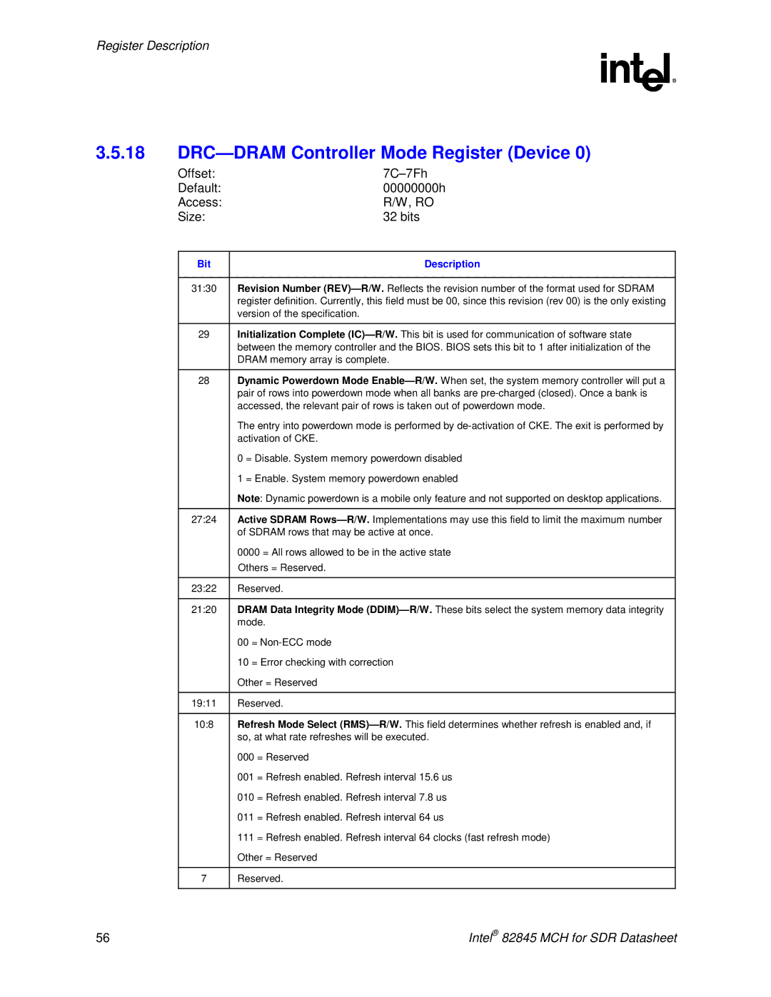
3.5.18DRC—DRAM Controller Mode Register (Device 0)
Offset: |
| |
Default: | 00000000h | |
Access: | R/W, RO | |
Size: | 32 bits | |
|
|
|
| Bit | Description |
|
|
|
| 31:30 | Revision Number |
|
| register definition. Currently, this field must be 00, since this revision (rev 00) is the only existing |
|
| version of the specification. |
|
|
|
| 29 | Initialization Complete |
|
| between the memory controller and the BIOS. BIOS sets this bit to 1 after initialization of the |
|
| DRAM memory array is complete. |
|
|
|
| 28 | Dynamic Powerdown Mode |
|
| pair of rows into powerdown mode when all banks are |
|
| accessed, the relevant pair of rows is taken out of powerdown mode. |
|
| The entry into powerdown mode is performed by |
|
| activation of CKE. |
|
| 0 = Disable. System memory powerdown disabled |
|
| 1 = Enable. System memory powerdown enabled |
|
| Note: Dynamic powerdown is a mobile only feature and not supported on desktop applications. |
|
|
|
| 27:24 | Active SDRAM |
|
| of SDRAM rows that may be active at once. |
|
| 0000 = All rows allowed to be in the active state |
|
| Others = Reserved. |
|
|
|
| 23:22 | Reserved. |
|
|
|
| 21:20 | DRAM Data Integrity Mode |
|
| mode. |
|
| 00 = |
|
| 10 = Error checking with correction |
|
| Other = Reserved |
|
|
|
| 19:11 | Reserved. |
|
|
|
| 10:8 | Refresh Mode Select |
|
| so, at what rate refreshes will be executed. |
|
| 000 = Reserved |
|
| 001 = Refresh enabled. Refresh interval 15.6 us |
|
| 010 = Refresh enabled. Refresh interval 7.8 us |
|
| 011 = Refresh enabled. Refresh interval 64 us |
|
| 111 = Refresh enabled. Refresh interval 64 clocks (fast refresh mode) |
|
| Other = Reserved |
|
|
|
| 7 | Reserved. |
|
|
|
56 |
| Intel® 82845 MCH for SDR Datasheet |