Testability
R
8 Testability
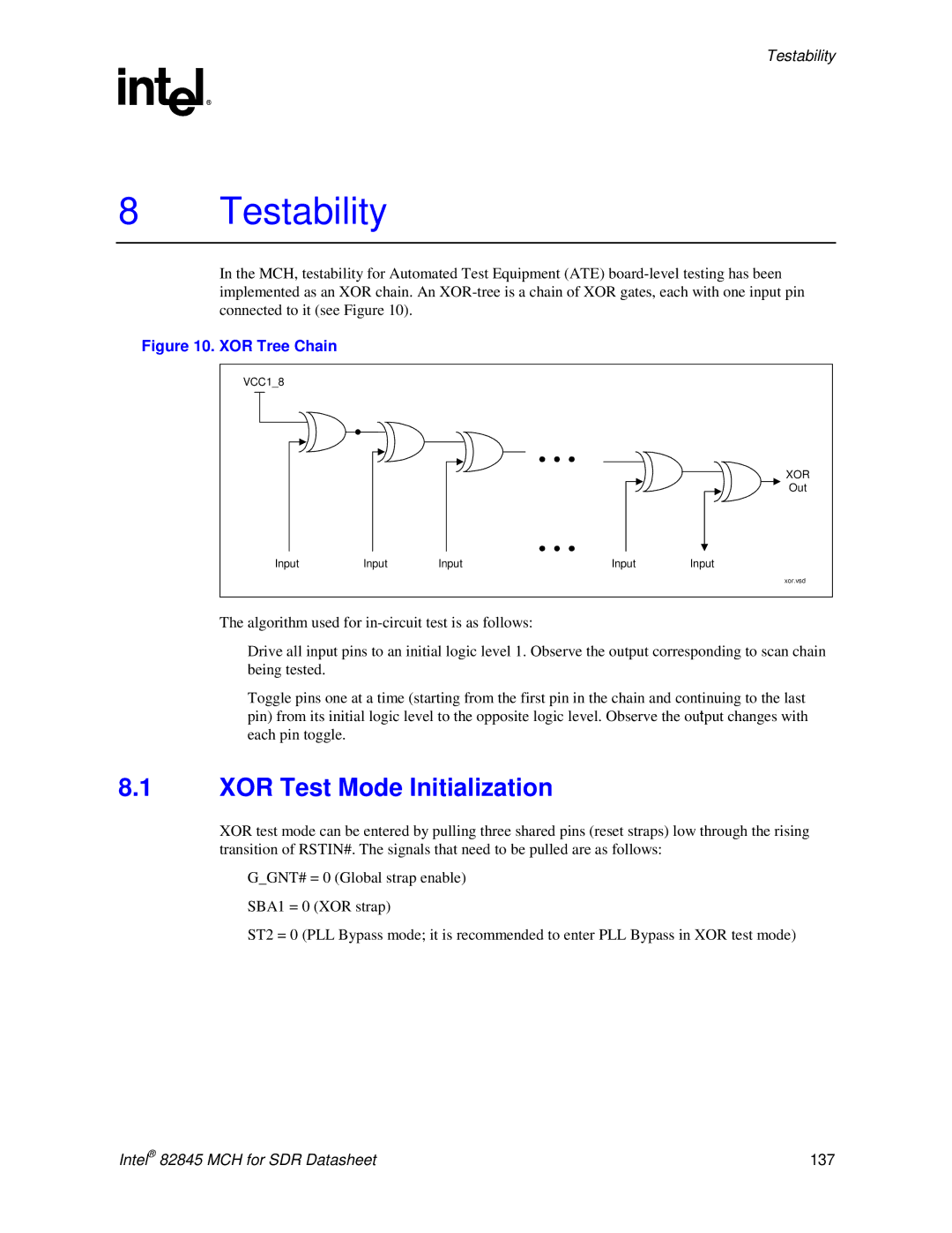
In the MCH, testability for Automated Test Equipment (ATE)
Figure 10. XOR Tree Chain
VCC1_8 |
|
|
|
|
|
|
|
| XOR |
|
|
|
| Out |
Input | Input | Input | Input | Input |
|
|
|
| xor.vsd |
The algorithm used for
•Drive all input pins to an initial logic level 1. Observe the output corresponding to scan chain being tested.
•Toggle pins one at a time (starting from the first pin in the chain and continuing to the last pin) from its initial logic level to the opposite logic level. Observe the output changes with each pin toggle.
8.1XOR Test Mode Initialization
XOR test mode can be entered by pulling three shared pins (reset straps) low through the rising transition of RSTIN#. The signals that need to be pulled are as follows:
•G_GNT# = 0 (Global strap enable)
•SBA1 = 0 (XOR strap)
•ST2 = 0 (PLL Bypass mode; it is recommended to enter PLL Bypass in XOR test mode)
Intel® 82845 MCH for SDR Datasheet | 137 |
