Register Description
R
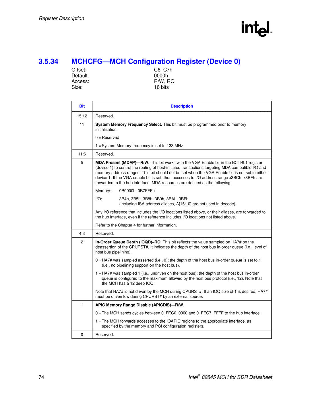
3.5.34MCHCFG—MCH Configuration Register (Device 0)
Offset: |
|
|
Default: |
| 0000h |
Access: |
| R/W, RO |
Size: |
| 16 bits |
|
|
|
Bit |
| Description |
|
|
|
15:12 | Reserved. |
|
|
| |
11 | System Memory Frequency Select. This bit must be programmed prior to memory | |
| initialization. |
|
| 0 = Reserved |
|
| 1 = System Memory frequency is set to 133 MHz | |
|
|
|
11:6 | Reserved. |
|
|
| |
5 | MDA Present | |
| (device 1) to control the routing of | |
| memory address ranges. This bit should not be set when the VGA Enable bit is not set in either | |
| device 1. If the VGA enable bit is set, then accesses to I/O address range | |
| forwarded to the hub interface. MDA resources are defined as the following: | |
| Memory: | |
| I/O: | 3B4h, 3B5h, 3B8h, 3B9h, 3BAh, 3BFh, |
|
| (including ISA address aliases, A[15:10] are not used in decode) |
| Any I/O reference that includes the I/O locations listed above, or their aliases, are forwarded to | |
| the hub interface, even if the reference includes I/O locations not listed above. | |
| Refer to the Chapter 4 for further information. | |
|
|
|
4:3 | Reserved. |
|
|
| |
2 | ||
| deassertion of the CPURST#. It indicates the depth of the host bus | |
| host bus pipelining). | |
| 0 = HA7# was sampled asserted (i.e., 0); the depth of the host bus | |
| (i.e., no pipelining support on the host bus). | |
| 1 = HA7# was sampled 1 (i.e., undriven on the host bus); the depth of the host bus | |
| queue is configured to the maximum allowed by the host bus protocol (i.e., 12). Note that | |
| the MCH has a 12 deep IOQ. | |
| Note that HA7# is not driven by the MCH during CPURST#. If an IOQ size of 1 is desired, HA7# | |
| must be driven low during CPURST# by an external source. | |
|
| |
1 | APIC Memory Range Disable | |
| 0 = The MCH sends cycles between 0_FEC0_0000 and 0_FEC7_FFFF to the hub interface. | |
| 1 = The MCH forwards accesses to the IOAPIC regions to the appropriate interface, as | |
| specified by the memory and PCI configuration registers. | |
|
|
|
0 | Reserved. |
|
|
|
|
74 | Intel® 82845 MCH for SDR Datasheet |
