Signal Description
R
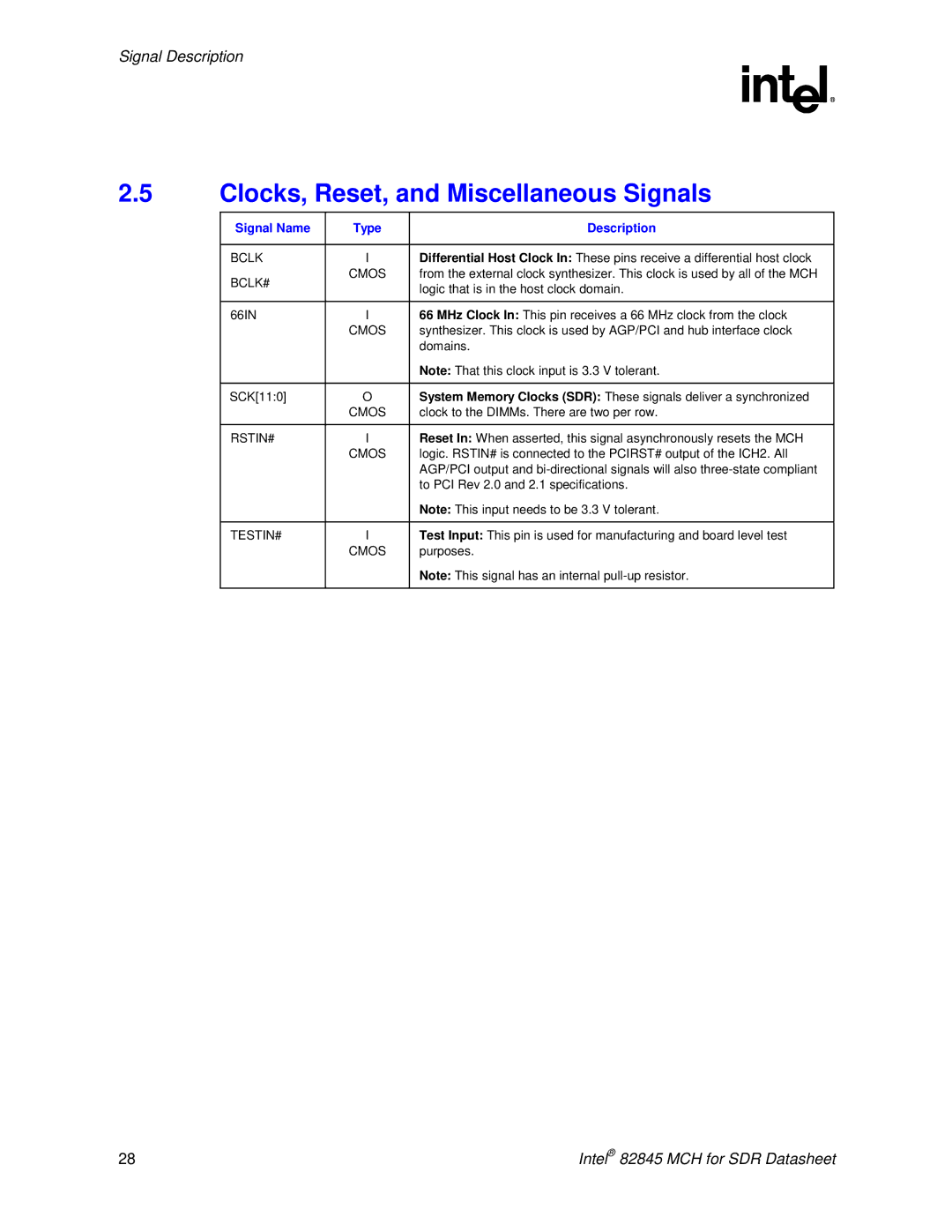
2.5Clocks, Reset, and Miscellaneous Signals
Signal Name | Type | Description |
|
|
|
BCLK | I | Differential Host Clock In: These pins receive a differential host clock |
BCLK# | CMOS | from the external clock synthesizer. This clock is used by all of the MCH |
| logic that is in the host clock domain. | |
|
| |
|
|
|
66IN | I | 66 MHz Clock In: This pin receives a 66 MHz clock from the clock |
| CMOS | synthesizer. This clock is used by AGP/PCI and hub interface clock |
|
| domains. |
|
| Note: That this clock input is 3.3 V tolerant. |
|
|
|
SCK[11:0] | O | System Memory Clocks (SDR): These signals deliver a synchronized |
| CMOS | clock to the DIMMs. There are two per row. |
|
|
|
RSTIN# | I | Reset In: When asserted, this signal asynchronously resets the MCH |
| CMOS | logic. RSTIN# is connected to the PCIRST# output of the ICH2. All |
|
| AGP/PCI output and |
|
| to PCI Rev 2.0 and 2.1 specifications. |
|
| Note: This input needs to be 3.3 V tolerant. |
|
|
|
TESTIN# | I | Test Input: This pin is used for manufacturing and board level test |
| CMOS | purposes. |
|
| Note: This signal has an internal |
|
|
|
28 | Intel® 82845 MCH for SDR Datasheet |