Register Description
R
Term | Description |
|
|
Reserved | In addition to reserved bits within a register, the MCH contains address locations in the |
Registers | configuration space that are marked “Reserved”. When a “Reserved” register location |
| is read, a random value is returned. (“Reserved” registers can be |
| size). Registers that are marked as “Reserved” must not be modified by system |
| software. Writes to “Reserved” registers may cause system failure. |
|
|
Default Value | Upon a Full Reset, the MCH sets all of its internal configuration registers to |
upon a Reset | predetermined default states. Some register values at reset are determined by |
| external strapping options. The default state represents the minimum functionality |
| feature set required to successfully bring up the system. Hence, it does not represent |
| the optimal system configuration. It is the responsibility of the system initialization |
| software (usually BIOS) to properly determine the DRAM configurations, operating |
| parameters and optional system features that are applicable, and to program the MCH |
| registers accordingly. |
|
|
3.2PCI Bus Configuration Space Access
The MCH and ICH2 are physically connected by the hub interface. From a configuration standpoint, the hub interface is PCI bus 0. As a result, all devices internal to the MCH and ICH2 appear to be on PCI bus 0. The system’s primary PCI expansion bus is physically attached to the ICH2 and, from a configuration perspective appears to be a hierarchical PCI bus behind a
The MCH contains two PCI devices within a single physical component. The configuration registers for the four devices are mapped as devices residing on PCI bus 0.
•Device 0:
•Device 1:
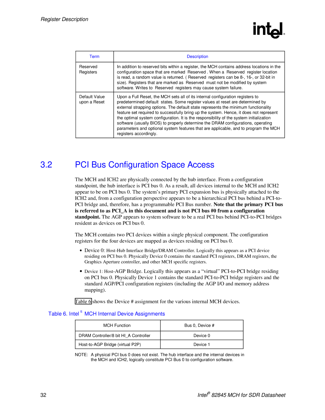
Table 6 shows the Device # assignment for the various internal MCH devices.
Table 6. Intel® MCH Internal Device Assignments
MCH Function | Bus 0, Device # |
|
|
DRAM Controller/8 bit HI_A Controller | Device 0 |
|
|
Device 1 | |
|
|
NOTE: A physical PCI bus 0 does not exist. The hub interface and the internal devices in the MCH and ICH2, logically constitute PCI Bus 0 to configuration software.
32 | Intel® 82845 MCH for SDR Datasheet |