Register Description
R
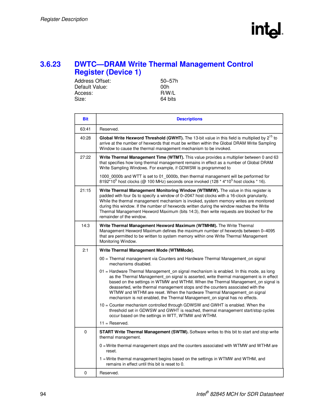
3.6.23DWTC—DRAM Write Thermal Management Control Register (Device 1)
Address Offset: |
| |
Default Value: | 00h | |
Access: |
| R/W/L |
Size: |
| 64 bits |
|
|
|
Bit |
| Descriptions |
|
|
|
63:41 | Reserved. |
|
|
| |
40:28 | Global Write Hexword Threshold (GWHT). The | |
| arrive at the number of hexwords that must be written within the Global DRAM Write Sampling | |
| Window to cause the thermal management mechanism to be invoked. | |
|
| |
27:22 | Write Thermal Management Time (WTMT). This value provides a multiplier between 0 and 63 | |
| that specifies how long thermal management remains in effect as a number of Global DRAM | |
| Write Sampling Windows. For example, if GDWSW is programmed to | |
| 1000_0000b and WTT is set to 01_0000b, then thermal management will be performed for | |
| 8192*105 host clocks (@ 100 MHz) seconds once invoked (128 * 4*105 host clocks * 16). | |
21:15 | Write Thermal Management Monitoring Window (WTMMW). The value in this register is | |
| padded with four 0s to specify a window of | |
| While the thermal management mechanism is invoked, system memory writes are monitored | |
| during this window. If the number of hexwords written during the window reaches the Write | |
| Thermal Management Hexword Maximum (bits 14:3), then write requests are blocked for the | |
| remainder of the window. |
|
|
| |
14:3 | Write Thermal Management Hexword Maximum (WTMHM). The Write Thermal | |
| Management Hexword Maximum defines the maximum number of hexwords between | |
| that are permitted to be written to system memory within one Write Thermal Management | |
| Monitoring Window. |
|
|
| |
2:1 | Write Thermal Management Mode (WTMMode). | |
| 00 = Thermal management via Counters and Hardware Thermal Management_on signal | |
| mechanisms disabled. |
|
| 01 = Hardware Thermal Management_on signal mechanism is enabled. In this mode, as long | |
| as the Thermal Management_on signal is asserted, write thermal management is in effect | |
| based on the settings in WTMW and WTHM. When the Thermal Management_on signal is | |
| deasserted, write thermal management stops and the counters associated with the | |
| WTMW and WTHM are reset. When the hardware Thermal Management_on signal | |
| mechanism is not enabled, the Thermal Management_on signal has no effects. | |
| 10 = Counter mechanism controlled through GDWSW and GWHT is enabled. When the | |
| threshold set in GDWSW and GWHT is reached, thermal management start/stop cycles | |
| occur based on the settings in WTT, WTMW and WTHM. | |
| 11 = Reserved. |
|
0START Write Thermal Management (SWTM). Software writes to this bit to start and stop write thermal management.
0= Write thermal management stops and the counters associated with WTMW and WTHM are reset.
1= Write thermal management begins based on the settings in WTMW and WTHM, and remains in effect until this bit is reset to 0.
0 | Reserved. |
94 | Intel® 82845 MCH for SDR Datasheet |