Revised July
Page
Word and is abbreviated Wd in documentation in this sense
Moderate injury, or property damage
Thing else
To the user
Omron
Trademarks and Copyrights
Table of Contents
Remote I/O Slave Communications 121
About this Manual
Manual Products Contents Cat. No
WS02-CXPC1-EV
Precautions
Intended Audience
General Precautions
Safety Precautions
Operating Environment Precautions
Operating Environment Precautions
Application Precautions
Application Precautions
Applicable Directives
Conformance to EC Directives
Concepts
Conformance to EC Directives
Xvii
Section
Section
Overview of DeviceNet
VME Master Boards
Overall System Configuration
Master Features DeviceNet Master Units and DeviceNet Units
Slave Features Terminals
Configurator Features
Environment-resistant Terminals
Remote Adapters
C200H I/O Link Units
Temperature Input Terminals
RS-232C Units
Multiple I/O TERMINALs
Applicable Units and DeviceNet Functions
Master Model Without Configurator With Configurator
Remote I/O Master
C200HX/HG/HE
C200HX/HG/HE CQM1H CQM1-DRT21
Remote I/O Slave only Units Mounted in a PC
CS1W-DRM21 CIO, WR, DM, EM, HR
CIO, DM, EM, AR, LR, T/C
Communications Instructions
Message Communications
Master Unit model Send Receive
Master model Model Capacity
Types of Slave
Communications Software Switches and Communications Status
Masters
Name Appearance Points Model number Remarks
DRT1-ND16S
DRT1-HD16S
DRT1-TS04T
DRT1-TS04P
DRT1-ID04CL-1
DRT1-ID04CL
DRT1-ID08CL
DRT1-ID08CL-1
Tion Number Supply Input Output Voltage
Multiple I/O Terminal Units
GT1-DA04MX
GT1-AD08MX
GT1-TS04T
GT1-TS04P
DeviceNet Configurator
DeviceNet Unit Features
Explicit Message Communications
Without the Configurator
Fins Message Communications
User-set allocations
Through a Serial Line
Configurator Connection
Tions. The maximum I/O for the slave function is 100 words
Programming
CX-Programmer
Monitoring of DeviceNet
Slave PCs Ver .1 or Later
Refer to 4-1 Master Remote I/O Communications for details
Methods
Various Connection
Maximum Network Length
500 m
General Specifications
Specifications
Functional and Performance Specifications
DeviceNet Unit
Figurator
Specifications
OUT
Section
Remote I/O Allocation method Fixed allo
CVM1/CV
Cations parameter settings, etc
CS1W-DRM21
Comparison between CS1W-DRM21 and CJ1W-DRM21
C200HW-DRM21-V1
Comparison with Previous Models
CS/CJ-series PC
Comparison with Previous Models
Using the Configurator 300 words total for
Eeprom
Models
Outline of the Configurator
Model Contents Personal Computer
Configurator Specifications
With no allocation area duplication
Hardware Preparations for Communications
Basic Operating Procedures
Network Installation Procedure
Sysmac Link Unit, Controller Link Unit, and Ethernet Unit
Creating Routing Tables
Tions to be used, as shown in the table below
Communications
Using the Master Function
Procedures Prior to Starting Communications
User-set Allocations Using Allocated DM Area Words
Fixed Allocations
User-set Allocations Using the Configurator
Using Slave Function
Section
Section
Situation Action
List of Usage Methods by Purpose
List of Usage Methods by Purpose
Nomenclature and Installation
Nomenclature and Functions
Indicators
Nomenclature and Functions
OFF
Status Indicators MS and NS
Indi Color Status Meaning likely errors
Seven-segment Digits
Seven-Segment Display
Following table shows the functions of the 7-segment digits
Status Display
Dot Indicators
Switch Settings
Following table shows the functions of the dot indicators
Unit No. Switch
Baud Rate
DIP Switch
System Configuration Precautions
Installing the DeviceNet Unit
Connectors
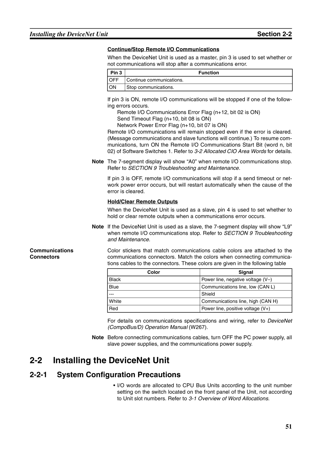
Continue/Stop Remote I/O Communications
CS-series
Mounting
CS-series, up to 16 Units can be mounted to the CS1W-BC
CJ-series
Handling Precautions
Carefully align the connectors to mount the DeviceNet Unit
Remove the label after wiring
External Dimensions
Allocated CIO and DM Words
Overview of Word Allocations
Unit number Allocated words
Allocated CIO Area Words
Allocated DM Area Words
Allocated CIO Area Words
Software Switches 1 Word n
Unit status area 2 word n+11 Master Status 1 word n+12
Mas Scan Unit Ter List Oper Func Sta Ating Tion Tus Mode
Word n n = CIO 1,500 + 25 x unit number
OFF→
List Oper Func Sta Ating Tion Tus
Mas
A C2 error will be displayed on
Mode Alloca Tions
Word n+1 n = CIO 1,500 + 25 x unit number
Software Switches 2 Word n+1
Slave Unit Func Oper Tion Ating Mode Reserved By system
Slave Unit Func Oper Tion Ating Mode
User Allocates the following words to the slave Pro
Scan Slave Unit
List Func Oper Sta Tion Ating Tus Mode
Disconnect/Connect Switches Words n+6 to n+9
Master COS Send Switches Words n+2 to n+5
Bit Name Status Controlled Unit operation
Word n+10 n = CIO 1,500 + 25 x unit number
Unit Status 1 Word n+10
Word n+11 n = CIO 1,500 + 25 x unit number
Unit Status 2 Word n+11
Itored from I/O Data Communications Flag word n+12 bit
Word n+12 n = CIO 1,500 + 25 x unit number
Master Status 1 Word n+12
Code Details
Master Status 2 Word n+13
Master I/O Allocation Status
Word n+14 n = CIO 1,500 + 25 x unit number
Slave Status 1 Word n+14
Tions Flag for Ter OUT 2/IN
Slave Status 2 Word n+15
List Enabled
Registered Slave Table Words n+16 to n+19
Master Node Addresses
Normal Slave Table Words n+20 to n+23
13 C200H Master Replacement Master Status 1 Word n+24
Word n+24 n = CIO 1,500 + 25 x unit number
ON/OFF
Unit Structure
Allocated DM Area Words
Communications Cycle Time Setup Table
Master User Allocations Setup Table
Code Name Word range
Enabled before you set these values
Areas and Word Ranges
Code Description Details
Allocation Size Setup Table
Setting Results
Setting Example
Slave User Allocations Setup Table
Word
Ranges
Communications Cycle Time Reference Table
Master User-set Allocations Reference Table
Slave User-set Allocations Reference Table
Slave Detailed Status
Figuration Slave with the scan list disabled Error Flags
COS
Remote I/O Master Communications
Master Communications
Master Remote I/O Communications
Allocations
Fixed Allocations
Using the Master User
User-set Allocations
Allocations Table
Section
Slave alloca Fixed allo
Remote I/O Master Specifications
Pattern One Master Unit Multiple Master Units connected
Precautions on the Number of Master Units
Numbers of Master Units when DeviceNet Units are used
Fixed Allocations for Remote I/O
Procedure for Using Remote I/O Master
User-set Remote I/O Allocations Using DM Area Settings
User-set Remote I/O Allocations Using the Configurator
Scan List
Scan List Contents
Through the allocated DM Through the Configurator
Scan List Enabled and Scan List Disabled
Creating the Scan List
Shown below
Fixed Allocations
Use a Software Switch to select the allocation area
Allocated Words
Backing Up the Scan List
Place the CPU Unit in Program mode Turn on
Procedure
Master Enable Switch
Select Fixed
Fixed Allocations Area
104
Node address Outputs Inputs Product
Changing System Components
Fixed Allocations Example
Turn on the Scan List
Enable Switch
Resulting Slave Allocation
User-set Allocations Methods
User-set Allocations
108
Setting the Master User Allocations Table
Procedure Turn on the Master Enable Switch
First word for the Allocation Size Setup Table
Setting the Allocation Size Setup Table
Turn on the Slave User Allocations Switch
Master User Allocations Table
Multiple masters cannot share the same slave
Changing System Components
Resulting Slave Allocations
Allocation Size Setup Table
Turning on the Master User Allocations Switch
113
Same node address cannot be allocated more than once
Procedure Step
Example of User-set Allocations Using the Configurator
Example of Ladder Programming for Remote I/O Communications
Starting and Stopping Remote I/O Communications
Starting Remote I/O Communications
Stopping Remote I/O Communications
Example of Ladder Programming for Remote I/O Communications
Condition Error Details Results Indicators Segment Display
Errors that May Occur in Remote I/O Communications
Following errors may occur during remote I/O communications
Condition Error Details Results Indicators
Remote I/O Slave Communications
Slave Communications
Slave Remote I/O Communications
Allocation Methods
Procedures for Using Remote I/O Slave Communications
Remote I/O and Slave Communications Specifications
124
Select a Fixed
Stop Slave
Allocation Area
Turn on the Slave
Fixed Allocation Area
Stop Slave Communications
Connection Types
Set the Slave User Allocations Table
Slave User Allocations Table
Areas and Word Ranges for the OUT 1/IN 1 Areas
Turn on the Slave User Allocations Switch word n+1, bit
Turn on the Slave Enable Switch
Slave areas
Block
Setting through
Configuration
Specified connection OUT 1 area 2 area Type
Connection Types and Allocated I/O Areas
Message Communications
Outline of Message Communications
Overview
OverviewSection
Fins messages Explicit messages
Fins Message Communications
Type of Fins message Data send/receive Fins commands
Overall Structure
Nodes masters and/or slaves that support Fins messages
Unit Series
Any Fins Command
DeviceNet Instructions
Master Unit To send
Receiving Fins Message Communications
Explicit Message Communications
Sending Fins Message Communications
Sages
Message Communications Specifications
Message Communications Error Indications
Message Communications Errors
Message Monitoring Timer
Fins Communications
Fins Commands and Responses
Indicators
Command Codes
Sending/Receiving Fins Command/Responses
Are required follow the command code
Response Codes
Commands Addressed to CS/CJ-series CPU Units
Fins Command Lists
Function Name Command Code
Units Supporting Fins Communications
Error Clear Error LOG Read Error LOG Clear
Function Name Command
Forced SET/RESET Forced SET/RESET Cancel
Clock Read Clock Write
Setting Node Addresses
Using Fins Message Communications
Commands Addressed to DeviceNet Units
Command to Send Explicit DeviceNet Messages
Relay network table, as described below
Routing Tables
Local Network Tables
Example
Table is created
Procedure for Creating the Routing Table
Relay Network Tables
Lowed on the way to the final network
Description
Data Send/Receive Instructions
Control Data
DeviceNet networks
Indicates a Unit as shown in the following table
Unit Setting
Response beginning at word D
Sending Fins Commands
Operating mode, and perform other functions at other nodes
Using SEND090, RECV098, and CMND490
Communications Flag Operation
Type Name Address Content Word Bit
Communications Flags
Communications Instructions Completion Codes
Following table
Timing of Reading Responses
Send/Receive Data Areas
Command Details
Example 1 Sending Data Using Send
Programming Examples
Operation
Bset
Program Example
Example 2 Sending a Fins Command Using Cmnd
Example Program
Connecting Networks for Fins Communications
Sending Explicit Messages
Sending Explicit Messages
Command Block Response Block
Fins Command Explicit Message Send 28
Error Responses
Normal Response
Sending Explicit Messages Using CMND490
162
Vendor code is read from a Slave Omron vendor code 002F Hex
Example Sending Explicit Messages Using CMND490
Following command is used Cmnd S D C
Response
Receiving Explicit Messages
PLC Objects provide the following services
List of PLC Object Services
Status Read/Write for CPU Units
ITOR, RUN
Memory Read/Write for CPU Units
Service Class ID Instance ID Request Contents Code Data
Command Block
CPU Information Read Service Code 0E Hex
Attribute ID Hex Contents Attribute value size
Hexadecimal
CPU Unit Write Service Code 10 Hex
Fffe
Error code Data cleared Hex
171
Operation Status
CPU Unit Status Read Service Code 40 Hex
Class ID command Always 002F Hex
173
Byte Data Read Service Code 1C Hex
Hexadecimal as shown in the following table
Areas for the PC you are using
To read the data is specified in hexadecimal as shown below
Data will be read to the high word
Data from is specified in hexadecimal as shown below
Word Data Read Service Code 1D Hex
Specified in hexadecimal as shown in the following table
Mal
Byte Data Write Service Code 1E Hex
You are using
Instance ID Hex CPU Unit memory area Word range For write
Word Data Write Service Code 1F Hex
Data areas for the PC you are using
Data is written is specified in hexadecimal as shown below
Other Functions
Connecting to the CX-Programmer via the DeviceNet
Use the Configurator to set the message monitoring timer
Setting the Message Monitoring Timer of the DeviceNet Unit
Setting the Message
Monitoring Timer
184
Response when Using the CX-Programmer via the DeviceNet
Memory Card Backup Functions
Outline of Functions
Backing Up Unit Setup Files
Restoring Unit Setup Files
File Names
Saving Files from Configurator to Memory Card
Communications Timing
Communications Cycle Time
Remote I/O Communications Characteristics
Communications Cycle Time and Refresh Time
Communications Time/Slave
Refresh Time
2 I/O Response Time
Maximum I/O Response Time
Slaves with More Than 8 Bytes of Input or Out put
Time PC Cycle Time
Communications Cycle
Minimum I/O Response Time
More than One Master in Network
System Startup Time
Case Slave’s indicator status
Master Function
Tions start up
Message Communications Time
Message Communications
Slave Function
Message Communications Only No Remote I/O Communications
Request from One Client Byte Data Read
Calculating the Maximum Message Response Time
198
Troubleshooting and Maintenance
Indicator status Network/Unit status Comments Segment
Troubleshooting with the DeviceNet Unit Indicators
Determining Operating Status from the Indicators
Error cate Indicators Gory Log Segment Hex
Troubleshooting Errors Occurring in the DeviceNet Unit
Master Errors
Use slaves with input and output areas of 200 bytes max
Segment MS indicator NS indicator Error log Hex
Set the slaves’ node addresses again
Inspect the slave and then create the scan list again
205
Check the following
Unit Status Error
Software Switch Setting Errors
CPU Unit Status Error
Incorrect Setting
Network Errors
Multiple Switches on
Network Power Error
Node Address Duplication Error
Transmission Timeout Error
Master’s node address is also set on another node
0342
Message Monitoring Timer List Logic Error Likely Cause
Memory Access Errors
Bus Off Detected
Bus Off condition was detected
211
Memory Access Error
Reset the master scan list
Unit Number duplication
CPU Unit Exchange Errors
CPU Unit Faulty H2
CPU Unit Memory Faulty
CPU Unit Faulty H6
CPU Unit Faulty Hb
Table Not Registered
Refresh Error
Routing Table Logic Error
There is an error in the contents of the routing table
Inspect the CPU Unit’s operating environment
Likely Cause CPU Unit Watchdog Timer Error
An error occurred in the CPU Unit
CPU Unit Fatal Error Output OFF Error
Slave Errors
Replace the CPU Unit
Output OFF Bit A50015 was turned on in the CPU Unit
Error Log Table
Error Log Functions
Unit Errors
Special Unit Error
Monitored and the data cannot be saved
Error Codes and Detail Codes
Time Information
Unit, the time stamp will contain all zeroes
220
221
CPU Unit’s ERR/ALM Indicator Lit or Flashing
Troubleshooting
Remote I/O Communications Disabled
Error Probable cause
Use the following table to troubleshoot I/O Link problems
3 I/O Link Problems
Use the following table to troubleshoot scan list problems
Communications Error Operation Settings
Tinuing/stopping communications for errors
Inspection
Maintenance and Replacement
Cleaning
Replacing Faulty Units
Creating a New Network File
Unit No. Set on rotary switches on front panel 0 to
Software Switches
Allocation Differences from C200H DeviceNet Master Units
Word address Bit
Master Status Area
Status Areas
DeviceNet Unit DRM21 status
C200HX Unit Unit Mas
C200HX Unit Unit Mas Word Series
Appendix a
Registered Slave Table
Communications Cycle Time Present Value
CS1W
CJ1W
Normal Slave Table
Replacing Ladder Programs from C200HW-DRM21-V1
Bit CS/CJ Series
CS/CJ Series C200HS
Replace the addresses as shown in the following table
Message Communications in Ladder Programs
Area type C200HW-DRM21-V1 This Unit CS1W Remarks
Instructions C200HW-DRM21-V1 This Unit CS1W Remarks
DeviceNet Connections
Connection Characteristics
Setting Connection Type
Connections Using Allocations
User-set allocations Using Configurator
Allocation method Contents
Connection Path
Fixed Allocation or User-set Allocations Using DM
Connection path settings cannot be made
Master COS Send Switch
239
Resets restarts the DeviceNet Unit
Reset
Resets the DeviceNet Unit
There are no responses for this command
Reads the internal status of the DeviceNet Unit
Baud rate
Space
Echoback Test
Test Data Command, Response
Reads the error history saved in the DeviceNet Unit
Read Error History
Error History Clear
Appendix C
Appendix D
Outline of Functions
Backing Up Unit Setup Files
Restoring Unit Setup Files
File Names
Saving Files from Configurator to Memory Card
Multi-vendor Applications
Connecting another Company’s Slaves to an Omron Master
Connecting an Omron Slave to another Company’s Configurator
Master Unit Device Profile
ID content Get read Set write Value
Object Mounting
Identity Object 01 Hex
DeviceNet Object 03 Hex
Appendix E
Connection Object 05 Hex
MAC ID
Section Information Max. No. of instances
ID content Get Set Value Read Write
Number of output bytes used by Slave
256
ACK
Format Transport class trigger
PC Object 2F Hex
Communications type Instance type
TIM/CNT
DeviceNet service Parameter option
PC area Refresh area type Refresh address
Explicit Message Send
When the explicit message execution failed or timed out
Command Command code
Appendix F
Index
Index
265
266
Cat. No. W380-E1-2
Revision History