DCP Configuration
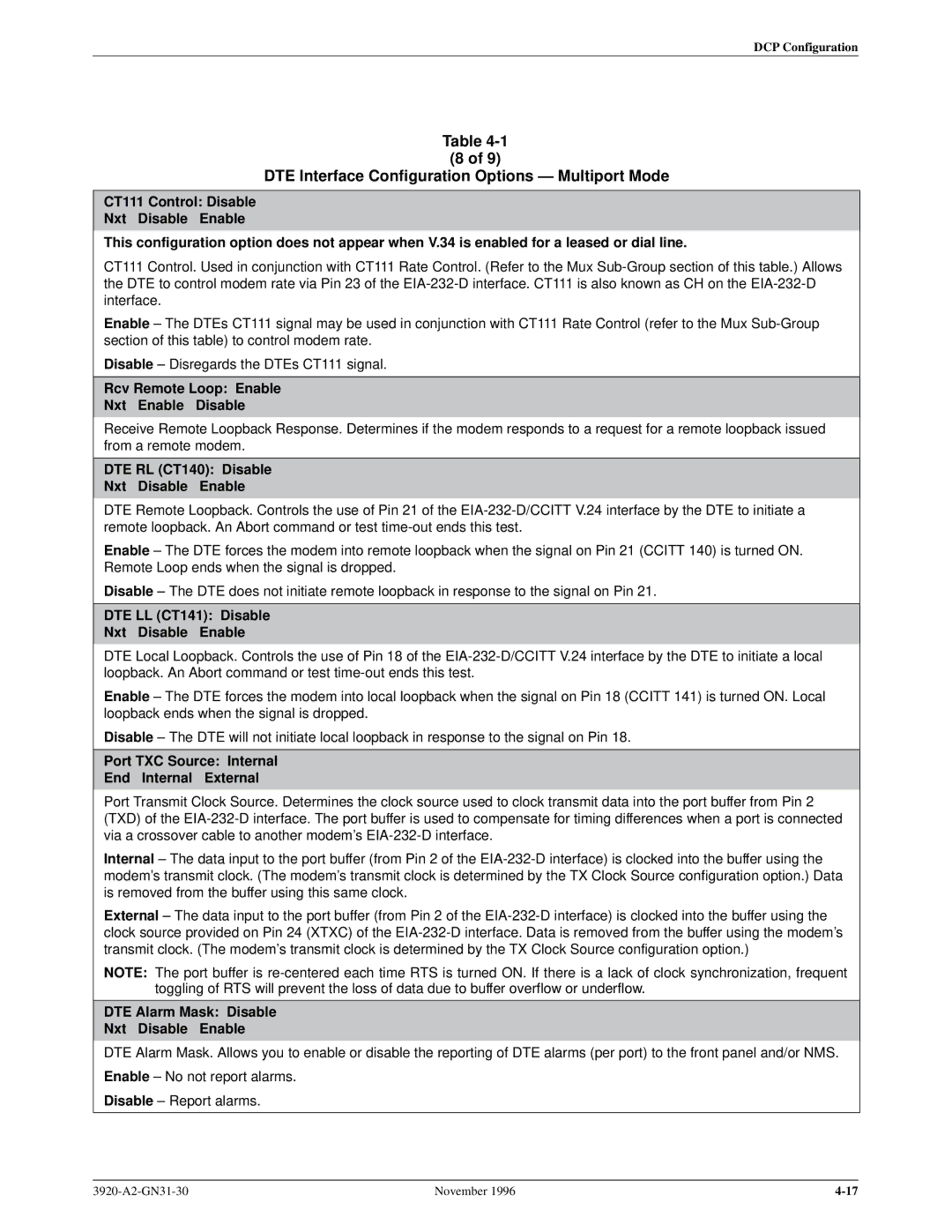
Table
(8 of 9)
DTE Interface Configuration Options Ð Multiport Mode l
CT111 Control: Disable
Nxt Disable Enable
This configuration option does not appear when V.34 is enabled for a leased or dial line.
CT111 Control. Used in conjunction with CT111 Rate Control. (Refer to the Mux
Enable ± The DTEs CT111 signal may be used in conjunction with CT111 Rate Control (refer to the Mux
Disable ± Disregards the DTEs CT111 signal.
Rcv Remote Loop: Enable
Nxt Enable Disable
Receive Remote Loopback Response. Determines if the modem responds to a request for a remote loopback issued from a remote modem.
DTE RL (CT140): Disable
Nxt Disable Enable
DTE Remote Loopback. Controls the use of Pin 21 of the
Enable ± The DTE forces the modem into remote loopback when the signal on Pin 21 (CCITT 140) is turned ON. Remote Loop ends when the signal is dropped.
Disable ± The DTE does not initiate remote loopback in response to the signal on Pin 21.
DTE LL (CT141): Disable
Nxt Disable Enable
DTE Local Loopback. Controls the use of Pin 18 of the
Enable ± The DTE forces the modem into local loopback when the signal on Pin 18 (CCITT 141) is turned ON. Local loopback ends when the signal is dropped.
Disable ± The DTE will not initiate local loopback in response to the signal on Pin 18.
Port TXC Source: Internal
End Internal External
Port Transmit Clock Source. Determines the clock source used to clock transmit data into the port buffer from Pin 2 (TXD) of the
Internal ± The data input to the port buffer (from Pin 2 of the
External ± The data input to the port buffer (from Pin 2 of the
NOTE: The port buffer is
DTE Alarm Mask: Disable
Nxt Disable Enable
DTE Alarm Mask. Allows you to enable or disable the reporting of DTE alarms (per port) to the front panel and/or NMS.
Enable ± No not report alarms.
Disable ± Report alarms.
November 1996 |