Retain for future use
April
Class a FCC Statement
Please Note
Contents
Power Factor Min/Max Conventions VAR Sign Conventions
Running the Diagnostics Wiring Error Test
Wire Pulse Initiator
Analog Input Example
Logging
Alarms
Waveform and Event Capture
Disturbance Monitoring
Appendix B-USING the Command Interface
Glossary Index
Schneider Electric All Rights Reserved
Figure A-1 Bits in a register 128
List of Figures
List of Figures 63230-300-212 April Viii
Summary of Circuit Monitor Instrumentation
List of Tables
List of Tables 63230-300-212 April
Introduction
Chapter Contents
Advanced features
What is the Circuit MONITOR?
From the display or remotely using software. -1summarizes
Readings available from the circuit monitor
Circuit Monitor Parts, Accessories, and Custom Cables
Accessories and Options for the Circuit Monitor
63230-300-212 Introduction April
Description Part Number Document Number
Topics not Covered
Features
This Bulletin
Introduction FirmwAre
Firmware
Introduction 63230-300-212 FirmwAre April
Safety Precautions
Safety Precautions 63230-300-212 April
Operation
Advanced features not accessible from the display
Operating the Display
Meters Resets Min/Max Setup View Alarms Diagnostics
Main Menu
How the Buttons Work
Display
Display Menu Conventions
Language English Date
MM/DD/YYYY
Operation 63230-300-212 Main Menu Overview April
Main Menu Overview
Setting Up the Display
Configuring the Circuit Monitor Using the Setup Menu
63230-300-212 Operation April
Setting Up the Communications
Factory Defaults for the Display Settings
Communications
Options for Communications Setup
Infrared Port
Ethernet Communications Card ECC Setup
Setting Up the Metering Functions of the Circuit Monitor
Meter
3Ø4W3CT
3Ø4W4CT2PT
Options for Meter Setup
Alarm from the display
Setting Up Alarms
Operation 63230-300-212
Setup and enable the new alarm
Create the custom alarm
Performing two steps
Create Custom
Options for Creating an Alarm
Alarm Parameters
Lbl Over THD Vbc Type Val Qty
THD
From the Main Menu, select Setup Alarm Edit Parameters
Follow these instructions to set up or edit an alarm
Dropout setpoints
Options for Editing an Alarm
Setup
Setting Up I/Os
Date & Time Display Communications Meter Alarm Passwords
KYZ
IOX Select Modules
Extender Setup
Custom
DI120AC
Descriptions
Configuring I/O Modules
Outputs for the I/O module you selected
Name Description
IOX Custom Setup
I/O Extender Setup selection menu displays
Input/Output Capabilities on
Passwords
Setting Up Passwords
Setup Diagnostics Engy/Dmd Reset Min/Max Reset
Creating Custom Quantities to be Displayed
Advanced Setup Features
Custom Quant Setup
Select Display Display Setup menu displays
Select a custom quantity
Options for Custom Quantities
Option Available Values Default
Custom Screen Setup
Select Custom Screen Custom Screen Setup screen displays
28 for instructions
Screen Blank Line
Screen
Monthly Energy Cost Blank Line
Screen Monthly Energy Cost Blank Line
Quantity Type Q Label Q
Available Default Quantities
Monthly Energy Cost Dollars
Viewing Custom Screens Advanced Meter Setup
Advanced Meter Setup
Select Meter Meter Setup screen displays
ABC
10 Options for Advanced Meter Setup
Main Menu Resets
Resetting MIN/MAX, DEMAND, and Energy Values
Reset Energy Reset Demand Reset MIN/MAX
Accumulated Power Demand Min/Max Amp Demand
Viewing Metered Data
Menus where you can view metered data in real time
Operation 63230-300-212 Viewing Metered Data April
Viewing Minimum and Maximum Values from the Min/Max Menu
Current Voltage Frequency Power Power Factor
MIN/MAX
Current a
Mn 01/22/2000159A Mx 01/22/2000815A
Meters Min/Max View Alarms Display Resets Setup Diagnostics
Viewing Alarms
View Alarms
Active Alarms List High Priority Log
Active Alarms List 1/1
Viewing Active Alarms
View and Acknowledging High Priority Alarms
High Priority Alarms
Digital Inputs Analog Inputs Digital Outputs Analog Outputs
Viewing I/O Status
Digital Outputs Kyzoff
Reading and Writing Registers
Diagnostics
READ/WRITE Regs
Reg Hex Dec 1003 000A
10 Wiring Error Test option on the Diagnostics menu
Performing a Wiring Error Test
Meter Information
Running the Diagnostics Wiring Error Test
Perform Test
Message Description
12 Wiring Error Messages
I2 load current less than 1% CT
Operation 63230-300-212 Performing a Wiring Check April
Circuit monitor
Metering Capabilities
More
REAL-TIME Readings
Readings
One-Second, Real-Time Readings Samples
100 ms Real-Time Readings
MIN/MAX Values for REAL-TIME Readings
63230-300-212 Metering Capabilities April
Included with the software
Power Factor Min/Max Conventions
To +0 on the same scale
Positive in this case
Reactive Power
Convention, refer to Advanced Meter Setup on
Real
ALT CM1 VAR Sign Convention IEEE/IEC VAR Sign Convention
Demand readings and their reportable ranges
Demand Readings
Demand Readings
Metering Capabilities 63230-300-212 Demand Readings April
April Demand Readings
Demand Power Calculation Methods
Block Interval Demand
Block Interval Demand Examples
Demand Voltage
Demand Current
Block Interval Demand on
April Demand Readings Synchronized Demand
Minutes for illustration purposes
Thermal Demand
Interval
Peak Demand Generic Demand
Input Pulse Demand Metering
For all channels
Channel pulse metering example
Energy Readings
Energy Readings
See Appendix A-Abbreviated Register Listing on page 127 for
April Energy Readings
Real Power
On page 68 summarizes the power analysis values
Power Analysis Values
Harmonic distortion
100%
April Power Analysis Values
Harmonic Power = Overall Power
Value Reportable Range
Power Analysis Values
On page 3 of this bulletin
INPUT/OUTPUT Capabilities
I /O Extender Options
Options
Input/Output Capabilities 63230-300-212 Options April
Extender Options
Digital Inputs
Command interface
59 in -Metering Capabilities for more about demand
Demand Synch Pulse Input
Calculations
To verify peak demand charges
Maximum value for each analog input
Analog Inputs
63230-300-212 Input/Output Capabilities April Analog Inputs
Analog Input Example
Has been configured as follows
Sample register readings for analog inputs
Input/Output Capabilities 63230-300-212 Analog Inputs April
Normal
Relay Output Operating Modes
Latched
April Relay Output Operating Modes
Timed
End Of Power Demand Interval
Absolute kWh Pulse
Absolute kVARh Pulse
Mechanical Relay Outputs
Setpoint-controlled Relay Functions
SOLID-STATE KYZ Pulse Output
Application
Wire Pulse Initiator
Calculating the KILOWATTHOUR-PER-PULSE Value
Analog Outputs
Sample register readings for analog output
Analog Output Example
Register Reading kW Output Current mA
Alarms
Alarms Groups
About Alarms
Alarms 63230-300-212 About Alarms April
Define the following information
Setpoint-Driven Alarms
Pickup Setpoint
Seconds, 100 ms increments, or cycles
Alarm Period
Pickup Delay Dropout Delay
Pickup Setpoint Dropout Setpoint
Alarms About Alarms
Priorities Alarm Levels
Alarms 63230-300-212 Custom Alarms April
Custom Alarms SETPOINT-CONTROLLED Relay Functions
Types of Setpoint-Controlled Relay Functions
63230-300-212 Alarms April
Undervoltage
Overvoltage
Phase Loss-Voltage
Phase Loss-Current
Reverse Power
Phase Reversal
Scale Factors on page 191 in Appendix B-Using the Command
Settings
Scale Factors
Setpoint
Alarms 63230-300-212 Scaling Alarm Setpoints April
Scaling Alarm Setpoints
Scale groups and their register numbers
Scale Group Register Numbers
Alarm Conditions and Alarm Numbers
Alarm Alarm Description Abbreviated Test Units Scale
List of Default Alarms by Alarm Number
Standard Speed Alarms 1 Second
Display Name Register
Display Name
High Speed Alarms 100 ms
Disturbance Monitoring 1/2 Cycle
Digital
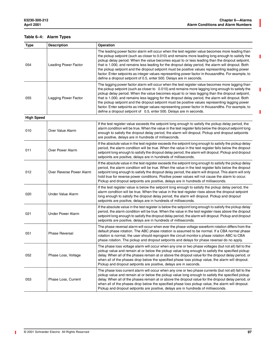
Alarm Types
Type Description Operation Standard Speed
High Speed
Type Description Operation
Boolean
Disturbance
Alarm Log Storage 100
See Factory Defaults on page 11 of the installation manual
102
Alarm Log Storage
Alarm LOG
Data Logs
101
April Data Logs
Min/Max Log Interval Min/Max/Average Log
MIN/MAX Logs
Logging 63230-300-212 Min/Max Logs April
102
Values Stored in Maintenance Log
Maintenance LOG
April Maintenance Log Interval Min/Max/Average Log Storage
Value Stored Description
Logging Memory Allocation
Memory Allocation
104
105
Memory allocation in SMS
Logging 63230-300-212 Memory Allocation April 106
107
107
Types of Waveform Captures
Available Resolutions for Disturbance Waveform Captures
Steady-state Waveform Capture
Disturbance Waveform Capture
Samples per Cycle Max. Duration Resolution
Available Resolutions for Adaptive Waveform Captures
Adaptive Waveform Capture
109
100ms rms Quantities
100ms rms Event Recording
110
Waveform Storage
Setting UP the Circuit Monitor for Automatic Event Capture
63230-300-212 Waveform and Event Capture April
111
112
HOW the Circuit Monitor Captures AN Event
113
Using SMS to gather data when a disturbance event occurs
114
113
About Disturbance Monitoring
115
April About Disturbance Monitoring
116
Capabilities of the Circuit Monitor During AN Event
Operate any output relays when the event is detected
63230-300-212 Disturbance Monitoring April
Categories CM-4000
Onboard Files tab
Onboard Alarms/Events tab
April Understanding the Alarm Log
Understanding the Alarm LOG
119
Schneider Electric All Rights Reserved
121
Monitor
Upgrading Memory in the Circuit Monitor 123
124
122
Upgrading Memory in the Circuit Monitor
Circuit Monitor Memory
April Circuit Monitor Memory
123
Meter Information
Identifying the Firmware Version
Xxxxxxxx
DOM
Information in -1 describes potential problems and their
Troubleshooting
Representative for assistance
126
Maintenance and Troubleshooting 63230-300-212 April
About Registers
April Contents
127
Currents and voltages
128
HOW Power Factor is Stored in the Register
Table A-1Date and Time Format
HOW Date and Time are Stored in the Register
Table A-2Date and Time Byte Example
Table A-3Abbreviated Register List
Register Listing
Register Description Scale Units Register Range Number
April Register Listing
Second Real-Time Readings
131
132
133
134
135
Real to Time Minimum Metered Values
136
137
138
139
Real to Time Maximum Metered Values
140
141
To 32,767 See How Power Factor is Stored in the Register on
142
143
144
Accumulated Energy
145
Demand
146
147
148
149
150
151
152
153
154
155
System Configuration
Phase Extremes
156
157
Current and Voltage Module Configuration
158
= Cvmt
159
Metering Configuration
160
161
162
163
164
165
Register Name Units Range Description Number
Table A-4Abbreviated Register List for I/O Status
167
Digital Input Template
169
Digital Output Template
KWH
Analog Output Template
Analog Input Template
171
First digit 4 indicates point is analog output
173
Table A-5Registers for Alarm Position Counters
174
175
176
177
Register Description Units Range Number
Table A-6Spectral Components
Template
178
179
180
Various operations
Issuing Commands 183 Point Numbers
181
181
Table B- 1 Location of the command interface
Overview of the Command Interface
182
Write the command code to command interface register
Issuing Commands
Table B- 2 Command Codes
8001-15
Resets
Setup
April Overview of the Command Interface
Files
185
186
Point Numbers
187
63230-300-212 Appendix B-Using the Command Interface April
Conditional Energy
Command Interface Control Digital Input Control
188
Incremental Energy
Using Incremental Energy
April Incremental Energy
189
Table B- 3 Registers for Harmonic Calculations
Setting UP Individual Harmonic Calculations
190
Changing Scale Factors
Schneider Electric All Rights Reserved
193
Glossary
Glossary 63230-300-212 April
Potential transformer PT-also known as a
194
Voltage transformer VT-seepotential
True power factor-seepower factor
195
Glossary 63230-300-212 April 196
197
INDEXNumerics
198
Index 63230-300-212 April
199
PLC
200
SMS
201
Index 63230-300-212 April 202
Page
PBG 1M 4/2001