AT Command Set
AC75 AT Command Set
Contents
Atsind
AT+CEER
ATS18
AT+CPAS
AT+CGMM
AT+GMM
AT+CGMR
AT+GMR
Atmonp
Atsals
Atshom
Atsplm
AT+CGACT
AT+CGANS
AT+CGAUTO
AT+CGDATA
AT+FRH
AT+FRM
AT+FRS
AT+FTH
Atsrsa
Atsrsm
Atssta
Sstn
AT+CCLK
AT+CALA
Atsad
Atsbc
23.3
List of Tables
List of Figures
SIM usage states of SAP server
Introduction
Scope of the document
Related documents
Quick reference table
Document conventions
PIN
Superscript notation for parameters and values
AT Command Syntax
Using Parameters
Combining AT commands on the same command line
Supported character sets
Ascii
Null
GSM alphabet tables and UCS2 character values
AC75 AT Command Set
GSM
2 UCS2 and GSM data coding and conversion for SMS text mode
UCS2
Case GSM IRA to 8 bit IRA to 16 bit
Software Flow Control XON/OFF Handshake
Serial Interface Flow Control
Hardware Flow Control RTS/CTS Handshake
AC75 AT Command Set
Communication between Customer Application and AC75
Unsolicited Result Code Presentation
Common PCN Handset Specification Cphs
CSP
Errors and Messages
AT&Fvalue
Configuration Commands
Valuenum
AT&Vvalue
AT&V Display current configuration
Activeprofile
1 AT&V responses
Active Profile
+FCLASS
+CGSMS
AC75 AT Command Set
ERROR/+CME Error err
AT&Wvalue
ATQ Set result code presentation mode
ATQn
ATV Set result code format mode
Error
Verbose and numeric result codes
ATVvalue
ATX Set Connect result code format and call monitoring
ATXvalue
AT\V Set Connect result code format
AT\Vvalue
ATZ Set all current parameters to user defined profile
ATZvalue
OK Error +CME Error
AT+CFUN Set phone functionality
AT+CFUN=?
+CFUN fun
Sysstart
Sysstart Charge only Mode
Funnum
Wake up the ME from Sleep mode
Rstnum
Fun=0
AT+CFUN=1
Atsmso Switch off mobile station
Smso MS OFF OK Error
ATSMSO=?
Atsmso
11 AT+GCAP Request complete TA capabilities list
AT+GCAP=?
AT+GCAP
+GCAP name
12 AT+CMEE Mobile Equipment Error Message Format
OK Error
AT+CMEE=?
AT+CMEE?
12.1 CME/CMS Error Code Overview
General CME Error Codes Siemens
SMS related CMS Error Codes GSM
No +CNMA ACK Expected
AC75 AT Command Set
AT+CSCS=?
13 AT+CSCS Select TE character set
AT+CSCS?
ATSCFG=?
Atscfg Extended Configuration Settings
AutoExecATC, time range of AutoExecPeriod
ATSCFG?
Scfg Userware/Stdout, if, intvalue, filename, logmode
Automatic AT command execution
Error +CME Error
Scfg Tcp/BufSize, tcpBufSize
Syslog Enabled Error +CME Error
Error +CME Error
Sysstart Airplane Mode
Scfg Stdout , if, intvalue, filename, logmode
EcATC at a given AutoExecIndex
AutoExecATC
Riod
AutoExecType value AutoExecType event
RFU
AutoExecATCstr+CSCS
AutoExecPeriodstr+CSCS
AutoExecPeriodTimeLeftstr+CSCS
Form a Gprs attach
Sysstart Airplane Mode appears
Psm9tostr+CSCS
Rbpstr+CSCS
TcpBufSizestr+CSCS
TcpWithUrcstr+CSCS
DeviceDescrstr+CSCS
OtapTracerstr+CSCS
DescrIndexstr+CSCS
Manufacturerstr+CSCS
Succstr+CSCS
Groid
USB
File
UDP
Filename and logmode
AT+CNMI=1,1
AT+CMGF=1
AT+CMGD=1
Smso MS OFF
Scfg
AT+CSCS=GSM
SM20CallMode, CmgwMode
ATSM20 Set M20 compatibility mode
ATSM20=CallMode, CmgwMode
Status Control Commands
AT+CMER Mobile Equipment Event Reporting
AT+CMER=?
AT+CMER?
Modenum
Keypnum
Dispnum
Indnum
AT+CIND=?
AT+CIND Indicator control
AT+CIND?
Also refer to .1, Call Status Information
No Carrier
Atsind Extended Indicator Control
ATSIND=indDescr, mode
ATSIND=?
ATSIND?
+CIEV indDescr, indValue
+CIEV indDescr, adnEntry, adnNumber, adnType, adnText
+CIEV indDescr, indValue, vmCounter
+CIEV indDescr, indValue, eonsOperator, servProvider
AC75 AT Command Set
AC75 AT Command Set
IndValuenum
Atsind only
AT+CIND
ATH
AT+CEER Extended Error Report
AT+CEER=?
AT+CEER
+CEER locationID, reason, ssRelease
Cause Location ID for the extended error report
AT+clck=oi,1,0000,3 +CME Error incorrect password
ATD01751223344
+CEER 8,21,0
GSM release cause for L3 Radio Resource RR
Siemens L2 cause
Siemens release cause for L3 Radio Resource RR
AC75 AT Command Set
Siemens release cause for L3 Mobility Management MM
GSM release cause for L3 Call Control CC
AC75 AT Command Set
GSM Release cause for Supplementary Service Call
Siemens release cause for L3 Call Control CC
GSM release cause for Session Management SM
Siemens release cause for Gprs API
GSM cause for L3 Protocol module or other local cause
Siemens release cause for PPP/IP-Stack
ATS18 Extended call release report
+CAUSE locationIDreason
ATS18?
ATS18=n
Busy
Connect 9600/RLP
AT+CPAS Mobile equipment activity status
AT+CPAS=?
AT+CPAS
+CPAS pas
AT+WS46 Select wireless network
AT+WS46=?
AT+WS46?
AT+WS46=n
AT\Q Flow control
Serial Interface Control Commands
AT\Qn
AT&Cvalue
AT&C Set Data Carrier Detect DCD Line mode
250 , Siemens
AT&D Set circuit Data Terminal Ready DTR function mode
AT&Dvalue
AT&S Set circuit Data Set Ready DSR function mode
AT&Svalue
ATE Enable command echo
ATEvalue
AT+ICF Serial Interface Character Framing
AT+ICF=?
AT+ICF?
+ICF format, parity
AC75 AT Command Set
AT+IFC=?
AT+IFC?
+IFC TEflowcontrol, TAflowcontrol
AT+IFC=TEflowcontrol, TAflowcontrol
AC75 AT Command Set
AT+ILRR=?
AT+ILRR Set TE-TA local rate reporting
AT+ILRR?
AC75 AT Command Set
AT+IPR Set fixed local rate
AT+IPR=?
AT+IPR?
+IPR rate
Autobauding
AT&W
AT+CMUX=?
10 AT+CMUX Enter multiplex mode
AT+CMUX?
Restrictions on Multiplex mode
AT&V
Second serial interface ASC1
+CME Error unknown
ATSTPB=?
ATSTPB?
Stpb n
Security Commands
AT+CPIN PIN Authentication
AT+CPIN=?
AT+CPIN?
New pintext
Pinstr
Codetext
What to do if PIN or password authentication fails?
AC75 AT Command Set
AT+CPIN2 PIN2 Authentication
AT+CPIN2=?
AT+CPIN2?
AT+CPIN2=pin, new pin
AT+CPIN2? +CPIN2 SIM PUK2
AT+CPBS=FD
Atspic Display PIN counter
ATSPIC=?
ATSPIC?
Atspic
At+cpin=9999 +CME Error incorrect password
Facilitystr
At+cpin?
+CPIN SIM PIN
+CPIN SIM PUK
+CPIN PH-SIM PIN
Spic PH-SIM PIN
Spic PH-SIM PUK
+CPIN Ready
OK +CREG
Spic SIM PIN2
AT+CLCK=facility, mode, password, class
AT+CLCK Facility lock
AT+CLCK=?
+CLCK status, class
Factory defined SIM locks
Passwordstr
Statusnum
Classnum
SMS
Mode=2
AT+CLCK=SC,1,9999
AT+CLCK=SC,0,9999
SIM PIN1
AT+CPIN? +CPIN SIM PIN
AT+CPIN=1111
AT+CPIN? +CPIN PH-SIM PIN
AT+CPIN=3333
ATSLCK=facility, mode, password, class
Atslck Facility lock
ATSLCK=?
Slck status, class
AT+CPWD Change Password
+CPWDlist of supported facility, password length
AT+CPWD=facility, old password, new password
Password length 4 to 8 digits
Password length 4 digits
Word authentication fails?
AT+CPIN2 command
AT+CPWD=PS,12345678,1111
AT+CPWD=PS,12345678
Atspwd Change Password
SPWDlist of supported facility, password length
ATSPWD=facility, old password, new password
+CME Error Operation not supported
ATSPWD=CM
Password length of CM 8 digits
Pass
Error CME Error
Atscsl Customer SIM Lock
ATSCSL=?
Scsl
PUKstr
Datastr
AT+CPBS?
+CPIN PH-NET PUK
AT+CPIN=11223344
Identification Commands
ATI Display product identification information
ATI
ATIvalue
AT+CGMI Request manufacturer identification
AT+GMI Request manufacturer identification
AT+CGMM Request model identification
AT+GMM Request model identification
AT+CGMR Request revision identification of software status
AT+GMR Request revision identification of software status
AT+GSN Request International Mobile Equipment Identity Imei
AT+CGSN=?
AT+CGSN
AT+GSN=?
AT+CIMI=?
AT+CIMI
Imsi
Imsistr
Call Status Information
Call related Commands
AT+CIND and AT+CMER
ATA Answer a call
ATA
Connect text
Textstr
ATDnmgsm
ATD Mobile originated call to specified number
No Dialtone
Mgsmstr
ATD03022222222
ATDmemnmgsm
Memstr
ATDSM15
AT+CPBR=1,xx
ATDLD9
Number
Responding field
ATDstrmgsm
Atdi Mobile originated call to Isdn number
ATDIn
Atdl Redial last number used
Atdl
ATH Disconnect existing connection
ATHn
AT+CHUP=?
10 AT+CHUP Hang up call
AT+CHUP
ATSHUP=cause, cn
ATSHUP=?
Causenum
AC75 AT Command Set
ATS0?
ATS0=n
ATS6?
13 ATS6 Set pause before blind dialing
ATS6=n
ATS7?
ATS7=n
ATS8?
ATS8=n
ATS10?
Carrier
ATS10=n
ATO Switch from command mode to data mode / PPP online mode
ATOn
18 +++ Switch from data mode to command mode
19 AT+CBST Select bearer service type
AT+CBST=?
AT+CBST?
+CBST speed, name, ce
Cenum&W
Non-transparent data calls
AT+CRLP=?
AT+CRLP?
+CRLP iws, mws, T1, N2
21 AT+CLCC List current calls of ME
AT+CLCC=?
AT+CLCC
+CLCC idx, dir, stat, mode, mpty, number, type, alpha
Numberstr
Mptynum
Typenum
Atslcc Siemens defined command to list current calls of ME
ATSLCC=?
ATSLCC?
Atslcc
Presentation of URC Slcc disabled
Statnum
Traffic channel assignednum
Slcc
Ring
23 AT+CR Service reporting control
+CR mode
AT+CR=?
AT+CR?
AT+CRC=?
AT+CRC?
+CSNS mode
25 AT+CSNS Single Numbering Scheme
AT+CSNS=?
AT+CSNS?
Atscni List Call Number Information
ATSCNI=?
Atscni
Scni id1,cs,number,type Scni id2,cs,number,type
Atslcd Display Last Call Duration
ATSLCD=?
Atslcd
Timestr
ATSTCD=?
Atstcd Display Total Call Duration
Atstcd
ATP Select pulse dialing
ATT Select tone dialing
ATP
ATT
Network Service Commands
AT+COPN Read operator names
AT+COPN=?
AT+COPN
AT+COPS Operator Selection
AT+COPS=?
AT+COPS?
+COPSmode, format, oper
AT+COPS=mode, format, oper
OpStatusnum
Or 3-digit Mobile Network Code MNC
ATSOPS=?
Atsops Extended Operator Selection
EonsTypenum
OpName
Formatnum
AT+CREG Network registration
AT+CREG=?
AT+CREG?
+CREG n, stat, lac, ci
Lacstr
AT+COPS=0
AT+CREG=2
+CREG 1,0145,291A
AT+CSQ Signal quality
AT+CSQ=?
AT+CSQ
+CSQ rssi,ber
ATSMONC=?
Atsmonc Cell Monitoring
Atsmonc
BSICnum
Channnum
Atsmond Cell Monitoring
ATSMOND=?
Atsmond
Smond sci, nci, TA, rssiber
RxQualnum
RxLevnum
Timeslotnum
Atsmond
SMOND262,01,3008,6060,32,100,66,,,0,,,0
Atsfnur Select the fixed network user rate
ATSFNUR=?
ATSFNUR?
Sfnur value
Atmoni Monitor idle mode and dedicated mode
ATMONI=?
Atmoni
ATMONI=period
Atmoni responses
MNC LAC
Service states
NCC BCC PWR
Atmonp Monitor neighbour cells
ATMONP=?
Atmonp
ATMONP=period
Atmonp responses
Chann DBm
MCC MNC BCC
100
Atsmong Gprs Monitor
ATSMONG=?
Atsmong
ATSMONG=table, period
Atsmong Cell Info Table
Gprs Monitor
Bcch Pbcch PAT MCC MNC NOM RAC
# Cell #
Atsals Alternate Line Service
ATSALS=?
ATSALS?
Sals view, line
ATSALS=1,1
Sals
Atshom Display Homezone
ATSHOM=?
Atshom
Shom homezonestate
Atsplm Read the Plmn list
ATSPLM=?
ATSPLM?
Atsplm
Rangenum
Numericstr
Indexnum
15 AT+CPOL Preferred Operator List
AT+CPOL=?
AT+CPOL?
+CPOL index, format, operator
Atsplr Read entry from the preferred operators list
ATSPLR=?
ATSPLR=index1, index2
Splr index1oper Splr index2oper
ATSPLW=?
Atsplw Write an entry to the preferred operators list
ATSPLW=index, oper
Supplementary Service Commands
AT+CACM Accumulated call meter ACM reset or query
AT+CACM=?
AT+CACM?
Atsacm Advice of charge and query of ACM and ACMmax
ATSACM=?
Atsacm
Sacm n, acm, acmMax
Ccmstr
AT+CAMM Accumulated call meter maximum ACMmax set or query
AT+CAMM=?
AT+CAMM?
+CAMM acmmax
AT+CAOC Advice of Charge information
AT+CAOC=?
AT+CAOC?
AT+CAOC
AT+CCUG Closed User Group
AT+CCUG=?
+CCUGn, index, info
AT+CCUG=n, index, info
Infonum
AT+CCFC=?
AT+CCFC Call forwarding number and conditions control
AT+CCFC=reason, mode, number, type, class, time
Timenum
Call Forwarding active
At+ccfc=0,0
At+ccfc=0,3,+493012345678,145
At+ccfc=0,4
At+ccfc=4,2 +CME error operation not supported at+ccfc=5,2
To query the status of CFU for all classes
AT+CCWA Call Waiting
AT+CCWA=?
AT+CCWA?
Scwa
Calling numberstr
Type of numbernum
CLI validitynum
At+ccwa=1
At+ccwa=,1
At+ccwa=,2
At+ccwa=1,1
AT+CHLD Call Hold and Multiparty
AT+CHLD=?
AT+CHLD=n
Udub
At+ccwa=1,1,1
+CCWA +491791292364,145,32,,0
At+chld=2
Hello
AT+CLIP Calling Line Identification Presentation
AT+CLIP=?
AT+CLIP?
+CLIP number, type, , , alpha, CLI validity
CLI has been withheld by the originator
10 AT+CLIR Calling Line Identification Restriction
AT+CLIR=?
AT+CLIR?
+CLIRn, m
11 AT+COLP Connected Line Identification Presentation
AT+COLP=?
AT+COLP?
+COLP number, type
Typenum
12 AT+CPUC Price per unit and currency table
AT+CPUC=?
AT+CPUC?
+CPUC currency, ppu
AT+CPUC=EUR,0.10,8888
+CME Error SIM PIN2 required
AT+CPUC=EUR,0.10
13 AT+CSSN Supplementary service notifications
AT+CSSN=?
AT+CSSN?
+CSSI code
Code 1num
Code 2num
14 AT+CUSD Unstructured supplementary service data
AT+CUSD=?
AT+CUSD?
AT+CUSD=n, strwrite, dcs
Dcsnum
Internet Service Commands
Access is provided to the following Internet Services
Maximum number of profiles defined / used
Address notation
Atsics Internet Connection Setup Profile
ConParmTag value
ATSICS=?
ATSICS?
ATSICS=conProfileId, conParmTag, conParmValue
Type
Alphabet
ARate
Mode
ConParmValuestr
ConParmValue-conTypestr
ConParmValue-alphabetstr
Example Default values of a CSD connection profile
ProfileId1
Example Gprs connection profile
Sici conProfileId, conState, numServices, conAddr
Atsici Internet Connection Information
ATSICI=?
ATSICI?
Checking Connection Profile Status
ConState=2 Up
Atsiss Internet Service Setup Profile
SrvParmTag
Smtp service
ATSISS=?
ATSISS?
Siss srvProfileId, srvParmTag, srvParmValue
ATSISS=srvProfileId, srvParmTag, srvParmValue
Smtp
POP3
AC75 AT Command Set
Content-Type multipart/mixed
PDelFlag
SrvParmValuestr
SrvParmValue-srvTypestr
SrvParmValue-alphabetstr
SrvParmValue-pCmdnum
SrvParmValue-pDelFlagnum
Atsisi Internet Service Information
ATSISI=?
ATSISI?
Sisi
UnackData
Atsiso Internet Service Open
ATSISO=?
ATSISO?
ATSISO=srvProfileId
LocAddrstr
SocketStatenum
RemAddrstr
SocketState=4
Atsisc=0
Siso Siso 4, Socket,3,3,0,0,10.10.0.18765534,0.0.0.00
ATSISC=?
Atsisc Internet Service Close
ATSISC=srvProfileId
Atsisr Internet Service Read Data
ATSISR=?
ATSISR=srvProfileId, reqReadLength
Sisr srvProfileId, urcCauseId
CnfReadLengthnum
ReqReadLength
UrcCauseIdnum
RemainUdpPacketLengthnum
Thisi
Sdata
Grama
RemainUdpPacketLength
Atsisw Internet Service Write Data
ATSISW=?
Sisw srvProfileId, urcCauseId
ReqWriteLengthnum
EodFlagnum
ReqWriteLength
OptServParamstr
CnfWriteLengthnum
Usage of parameter eodFlag
No further user data is accepted
Http / POP3
Atsico Internet Connection Open
ATSICO=?
ATSICO?
Sico conProfileId, conParmTag, conParmValue
ConParmTagstr
ATSICC=?
Atsicc Internet Connection Close
ATSICC=conProfileId
ATSISX=service, conProfileId, address, request, timelimit
Atsisx Internet Service Execution
ATSISX=?
PingInfoType =1
Atsics
InfoType =1
10.11.1 Example Ping
MaxRTTnum
MeanRTTnum
Sisx Ping,2,1,4,4,0,0 Sisx Ping,3,1,415,1043,643
Atsise Internet Service Error Report
ATSISE=?
ATSISE=srvProfileId
Sise srvProfileId, infoID, info
Internet Service URC SIS
SIS srvProfileId, urcCause, urcInfoId, urcInfoText
UrcCausenum
UrcInfoIdnum
UrcInfoTextstr
Information Elements Related to the Service Application
UrcInfoId urcInfoText
Information Elements Related to FTP Service
FoId and the urcInfo
Text
PPP LCP Failed
Information Elements Related to POP3 Service
Information Elements Related to Http Service
Information Elements Related to Smtp Service
Configuring Socket Listener
Selecting URC Mode or Polling Mode
With Atsiso
ATSISO=0
Socket Client Sends Data via TCP Connection Polling Mode
ATSISI=0
Socket client sends data via TCP connection with URCs
Configuring and Using FTP Download URC Mode
ATSISC=0
Configuring and Using FTP Upload URC Mode
Configuring Smpt Service Profile
Sending Email URC Mode
Sending Email Polling Mode
Configuring POP3 Service Profile
Retrieving Email Polling Mode
Retrieving Email URC Mode
CET
Http Post Polling Mode
Http GET Polling Mode
Gprs Commands
11.1 AT+CGACT PDP context activate or deactivate
AT+CGACT=?
AT+CGACT?
11.1 AT+CGACT
Cidnum
Connect No Carrier Error +CME Error
AT+CGANS=?
AT+CGANS=response, L2P, cid
Responsenum
AC75 AT Command Set
11.3 AT+CGATT Gprs attach or detach
AT+CGATT=?
AT+CGATT?
State=1
AT+CGANS command
AT+CGAUTO=?
AT+CGAUTO?
+CGAUTO n
AC75 AT Command Set
AT+CGDATA=?
11.5 AT+CGDATA Enter data state
AT+CGDATA=L2P, cid, cid
Automatic deactivation of PDP context during dial-up PPP
11.6 AT+CGDCONT Define PDP Context
AT+CGDCONT=?
AT+CGDCONT?
+CGDCONT cid, PDPtype, APN, PDPaddr, dcomp, hcomp
APNstr
PDPaddrstr
Dcompnum
Hcompnum
AT+CGEQMIN=?
AT+CGEQMIN?
Guaranteed bitrate ULnum
Guaranteed bitrate DLnum
Traffic classnum
Maximum bitrate ULnum
SDU error ratiostr
Residual bit error ratiostr
Maximum SDU sizenum
Delivery of erroneous SDUsnum
Transfer delaynum
Traffic handling prioritynum
AT+CGEQREQ=?
11.8 AT+CGEQREQ 3G Quality of Service Profile Requested
AT+CGEQREQ?
Traffic classnum
Maximum SDU sizenum
Transfer delaynum
11.9 AT+CGPADDR Show PDP address
AT+CGPADDR=?
AT+CGPADDR=cid,cid
+CGPADDR cid, PDPaddress
+CGQMIN cid, precedence, delay, reliability, peak, mean
AT+CGQMIN=cid, precedence, delay, reliability, peak, mean
AT+CGQMIN=?
AT+CGQMIN?
Delaynum Delay class
Precedencenum
Reliabilitynum
Peaknum
Meannum
AT+CGDCONT=1,IP OK AT+CGQMIN=
11.11 AT+CGQREQ Quality of Service Profile Requested
+CGQREQ cid, precedence, delay, reliability, peak, mean
AT+CGQREQ=cid, precedence, delay, reliability, peak, mean
AT+CGQREQ=?
Delaynum
AT+CGDCONT=1,IP AT+CGQREQ=
+CGQREQ1,0,0,0,0,0
11.12 AT+CGREG Gprs Network Registration Status
AT+CGREG=?
AT+CGREG?
+CGREG n, stat, lac, ci
Plmn
Stat=1 or stat=5
11.13 AT+CGSMS Select service for MO SMS messages
+CGSMS service
AT+CGSMS=?
AT+CGSMS?
Atsgact Query all PDP context activations
ATSGACT=?
ATSGACT?
Sgact ifc, cid, state
Sumnum
ATSGAUTH=?
Atsgauth Set type of authentication for PPP connection
ATSGAUTH?
ATSGCONF=?
Atsgconf Configuration of Gprs related Parameters
ATSGCONF?
AC75 AT Command Set
Connect No Carrier
11.18 ATD*99# Request Gprs service
ATD*99* calledaddress* L2P* cid#
Calledaddressstr
PPP
11.19 ATD*98# Request Gprs IP service
ATD*98* cid#
11.20 ATH
11.21 ATS0
Using Gprs AT commands Examples
AT+CGDCONT=1,IP
AT+CGDCONT=2,IP, internet.t-d1.gprs
AT+CGDCONT=1
AT+CGQREQ=1,2
AT+CGQREQ=1
AT+CGACT=1,2
AT+CGACT=
Using the Gprs dial command ATD
By AT+CGDCONT
FAX Commands
FAX parameters
Fax Result Codes
AT+FCLASS Parameter
12.2 AT+FCLASS Fax Select, read or test service class
AT+FCLASS=?
AT+FCLASS?
AT+FCLASS=n
12.3 AT+FRH Receive Data Using Hdlc Framing
AT+FRH=?
AT+FRH=mod
TIA/EIA-578
AT+FRM=?
12.4 AT+FRM Receive Data
AT+FRM=mod
12.5 AT+FRS Receive Silence
AT+FRS=time
AT+FTH=?
12.6 AT+FTH Transmit Data Using Hdlc Framing
AT+FTH=mod
AT+FTM=?
12.7 AT+FTM Transmit Data
AT+FTM=mod
12.8 AT+FTS Stop Transmission and Wait
AT+FTS=time
Short Message Service SMS Commands
SMS parameters
Ackpdunum
Cdatanum
Ieianum
Lengthnum
Maxnum
Mem1str
Mem3str
Midnum
Pagenum
Pagesnum
Refnum
Sctsnum
Seqnum
Statstr
Todanum
Tooanum
Toranum
Toscanum
13.2 AT+CMGC Send an SMS command
Error +CMS Error
AT+CMGC=?
+CMGC mr, scts
OK Error +CMS Error
13.3 AT+CMGD Delete short message
AT+CMGD=?
AT+CMGD=index
+CMGF mode
13.4 AT+CMGF Select SMS message format
AT+CMGF=?
AT+CMGF?
AT+CMGL=?
13.5 AT+CMGL List SMS messages from preferred store
AT+CMGL
AC75 AT Command Set
13.6 AT+CMGR Read SMS messages
AT+CMGR=?
+CMGR stat, fo, mr, ra, tora, scts, dt, st Data
+CMGR stat, fo, ct, pid, mn, da, toda, length Data
AC75 AT Command Set
13.7 AT+CMGS Send Short Message
AT+CMGS=?
+CMGS mr, scts
+CMGS mr, ackpdu
AC75 AT Command Set
13.8 AT+CMGW Write Short Messages to Memory
AT+CMGW=?
AT+CMGW
+CMGW index
AC75 AT Command Set
13.9 AT+CMSS Send short messages from storage
AT+CMSS=?
AT+CMSS=index, da, toda
+CMSS mr, scts
AT+CNMA
AT+CNMA=?
AT+CNMA=n
AT+CNMI=?
13.11 AT+CNMI New short Message Indication
AT+CNMI?
+CBM lengthCRLFpdu
+CBM sn, mid, dcs, page, pagesCRLFdata
+CDS lengthCRLFpdu
+CDS fo, mr, ra, tora, scts, dt, st
Unsolicited result code
OK Error Error +CMS Error
13.12 AT+CPMS Preferred SMS message storage
AT+CPMS=?
AT+CPMS?
AC75 AT Command Set
13.13 AT+CSCA SMS Service Center Address
AT+CSCA=?
AT+CSCA?
+CSCA sca, tosca
13.14 AT+CSCB Select Cell Broadcast Message Indication
AT+CSCB=?
AT+CSCB?
+CSCB mode, mids, dcss
AT+CSDH=?
13.15 AT+CSDH Show SMS text mode parameters
AT+CSDH?
13.16 AT+CSMP Set SMS text Mode Parameters
AT+CSMP=?
AT+CSMP?
+CSMPfo, vp/ scts, pid, dcs
Pidnum
AT+CSMS=?
13.17 AT+CSMS Select Message Service
AT+CSMS?
Bmnum
ATSCML=?
Atscml
Scml index, stat, fo, mr, ra, tora, scts, dt, st
Scml index, stat, fo, ct
Atscmr Read Concatenated Short Messages
ATSCMR=?
Atscms Send Concatenated Short Messages
ATSCMS=?
ATSCMW=?
Atscmw Write Concatenated Short Messages to Memory
Scmw index
ATSLMS=?
Atslms List SMS Memory Storage
Atslms
Atsmgl
ATSMGL=?
ATSMGL=stat
Smgo n, mode
OK Error CME Error
ATSMGO=?
ATSMGO?
AC75 AT Command Set
ATSMGR=?
Smgr
ATSMGR=index
See AT+CMGR
Atssconf SMS Command Configuration
ATSSCONF=?
ATSSCONF?
ATSSCONF=ra
Atssda Set SMS Display Availability
ATSSDA=?
ATSSDA?
SSDAda
Atssmss Set Short Message Storage Sequence
ATSSMSS=?
ATSSMSS?
Ssmss seq
14.1 AT+CRSM Restricted SIM Access
SIM related Commands
AT+CRSM=?
AT+CRSM=command, fileID, P1, P2, P3, data
Commandnum
+CRSM sw1,sw2,response
FileIDnum
Sw2num
Responsestr
14.2 AT+CSIM Generic SIM Access
AT+CSIM=length, command
Length of command or response string
AT+CSIM=?
AT+CSIM=14,A0A40000026F3A
+CSIM 4,9F0F
Atsatr Query SIMs Answer to Reset Data
ATSATR=?
Atsatr
Satr response
Atsxsm Extended SIM Access
ATSXSM=command, fileID, P1, P2, P3, data
ATSXSM=?
Sxsm sw1, sw2,response
3445566778899AABBCCDDEEFF
Sxsm
Atscks Query SIM and Chip Card Holder Status
ATSCKS=?
ATSCKS?
Scks mode, SimStatus
ATSCKS=1
SimStatusnum&V
Scks
Atsset Indicate SIM data ready
ATSSET=?
ATSSET?
Ssim Ready
Atscid Display SIM card identification number
ATSCID=?
Atscid
Scid cid
14.8 AT+CXXCID Display card ID
AT+CXXCID=?
AT+CXXCID
+CXXCID cid
Remote SIM Access RSA Commands
SAP server
SAP client
ATSRSA=?
Atsrsa Remote SIM Access Activation
ATSRSA?
SapRolenum
DevIdnum
MuxChannum
DataFormnum
BeaconPernum
DiscTypenum
URC Srsa devId , sapRole , connState , linkChange
ConnStatenum
LinkChangeCausenum
Atsrsm Remote SIM Access Message
ATSRSM=?
ATSRSM=RsaDevId, RsaMsgId, RsaMsgData, RsaMsgLen, RsaMsgRc
Srsm RsaDevId, RsaMsgId, RsaMsgData, RsaMsgLen, RsaMsgRc
MaxMsgSizenum
ConnStatusnum
CmdApdustr
CmdApduLennum
AT+CREG=1
ATSSET=1
SRSA0
SCKS0
SAP Request Message Parameters
SAP Response Message Parameters
Bluetooth scenario SAP
Related AT Commands
Establishing an RSA Connection in a PC Environment
Serial Interface Scenario Xsap
SIM Application Toolkit SAT Commands
Atssta SAT Interface Activation
ATSSTA=?
ATSSTA?
AllowedInstancenum
Alphabetnum
SatProfilestr
Sstn cmdType
Sstn SAT Notification
Sstn cmdTerminateValue
Atsstgi SAT Get Information
ATSSTGI=?
ATSSTGI?
Sstgi state, cmdType
Atsstr SAT Response
ATSSTR=?
ATSSTR?
Sstr state, cmdType
Phonebook Commands
Sort Order for Phonebooks
17.2 AT+CNUM Read own numbers
AT+CNUM=?
AT+CNUM
+CNUM alpha, number, type
17.3 AT+CPBR Read from Phonebook
AT+CPBR=?
+CPBR 1-maxloc,nlength, tlength
AT+CPBR=location1, location2
Nlengthnum
Maxlocnum
Tlengthnum
+CPBR1-100,20,17
17.4 AT+CPBS Select phonebook memory storage
AT+CPBS=?
+CPBS storage, used, total
AT+CPBS=storage
Usednum
Totalnum
17.5 AT+CPBW Write into Phonebook
AT+CPBW=?
+CPBW 1-maxloc,nlength, list of supported types, tlength
AT+CPBW=location, number, type, text
Typenum
AT+CPBW=,+431234567,145,international
AT+CPBW=1
Atspbw Write into Phonebook with location report
ATSPBW=?
Spbw 1-maxloc,nlength, list of supported types, tlength
ATSPBW=location, number, type, text
Typenum
ATSPBW=3
ATSDLD=?
Atsdld Delete the last number redial memory
Atsdld
Atspbc Find first matching entry in sorted phonebook
ATSPBC=?
ATSPBC=schar
Spbc index
ATSPBD=?
Atspbd Purge phonebook memory storage
ATSPBD=storage
Atspbg Display phonebook entries in alphabetical order
ATSPBG=?
Spbg 1-used,nlength, tlength
ATSPBG=index1, index2, RealLocReq
RealLocReqnum
Using Atspbg with RealLocReq
Using Atspbg without RealLocReq
AT+CPBR=27
Atspbs Step through the selected phonebook alphabetically
ATSPBS=?
ATSPBS=value, RealLocReq
Index-anum
Counter value
Index-bnum
Index-b=index-a+1
Index-cnum
Internal-counternum
At&f
Atspbs=2
SPBS33,+49301234567,145,TomTailor
At+cpbr=27
Audio Commands
Audio programming model
ATM Set monitor speaker mode
ATL Set monitor speaker loudness
ATLval
Valnum
18.4 AT+CLVL Loudspeaker volume level
AT+CLVL=?
AT+CLVL?
AT+CFUN=1,1
AT+CMUT=?
18.5 AT+CMUT Mute control
AT+CMUT?
18.6 AT+VTD Tone duration
AT+VTD=?
AT+VTD?
Duration
18.7 AT+VTS Dtmf and tone generation
AT+VTS=?
AT+VTS=dtmfString
AT+VTS=dtmf, duration
Atsaic Audio Interface Configuration
ATSAIC=?
ATSAIC?
Saic io, mic, ep, clock, mode, framemode
FramemodenumSNFW
ATSNFA=?
Atsnfa Set or query of microphone attenuation
ATSNFA?
OK atsnfa? Snfa OK atsnfs=4 OK atsnfa=1 OK atsnfi? Snfi 5,1
OK atsnfa? Snfa
ATSNFD=?
Atsnfd Set audio parameters to manufacturer default values
Atsnfd
Atsnfi Set microphone path parameters
ATSNFI=?
ATSNFI?
Snfi inBbcGain, inCalibrate
Atsnfm Set microphone audio path and power supply
Snfm MicSwitch, MicVccState
ATSNFM=MicSwitch, MicVccCtl
ATSNFM=?
MicVccStatenum
ATSNFO=?
Atsnfo Set audio output = loudspeaker path parameter
ATSNFO?
AC75 AT Command Set
Atsnfpt Set progress tones
ATSNFPT=?
ATSNFPT?
Snfpt pt
ATSNFS=?
Atsnfs Select audio hardware set
ATSNFS?
ATSNFS=4 ATSAIC?
ATSNFS=2 ATSAIC?
Atsnfw
ATSNFS=4
ATSAIC=2,1,1
Atsnftty Signal TTY/CTM audio mode capability
ATSNFTTY=?
ATSNFTTY?
Snftty audioState
Atsnfv Set loudspeaker volume
ATSNFV=?
ATSNFV?
Snfv outStep
Atsnfw Write audio setting in non-volatile store
ATSNFW=?
Atsrtc Ring tone configuration
ATSRTC=?
ATSRTC?
Atsrtc
Volumenum
Hardware Related Commands
Error OK
19.1 AT+CCLK Real Time Clock
AT+CCLK=?
19.2 AT+CALA Set alarm time
AT+CALA=?
AT+CALA?
+CALA time, n, type, text
Sysstart Airplane Mode +CALA text
+CALA text
Atsmso Smso MS OFF OK Shutdown
Sysstart Airplane Mode +CALA Good Morning
AT+CALA= OK AT+CALA?
SAD diag +CME Error err
Atsad Antenna Diagnosis
ATSAD=?
Atsad
Atsbc Battery Charge Control
ATSBC=?
ATSBC?
SBC bcs, bcl, mpc
SBC Overvoltage warning
SBC Overvoltage shutdown
Bcsnum
Bclnum
Responses returned by read command
Atsbv Battery/Supply Voltage
ATSBV=?
Atsbv
SBV value
ATSCTM?
ATSCTM=?
Sctm n, m, temp
Tempnum
Deferred shutdown
Sctma
Sctmb
Sctma
Atssync Configure Sync Pin
ATSSYNC=?
ATSSYNC?
SSYNCmode
ME status indicated by status LED patterns
AC75ATCV01.002 495 10/30/06 Confidential / Released
ATSSPI=?
Atsspi Serial Protocol Interface
ATSSPI?
BasicConfigurationnum
DelayOnenum
DelayTwonum
ExtendedSpiConfigurationnum
Specifying Delay Time for I²C
2 , Selecting SPI Mode
Selecting SPI Mode
Transmitting Data over AT Interface
Channel Open / Close
Structure of Messages on the I²C Bus
Message syntax
Error Handling on the I²C Bus
Structure of Messages on the SPI
Not Acknowledge
Example Using I²C Bus
Example Transfer and Response Messages on SPI
+ 11 22 33 44 ... FF
+ 44 55 66 77 88 99 AA BB
+ AA BB CC DD
Atswdac Configure and Read PWM Signal for DAC
ATSWDAC=?
ATSWDAC?
Swdac dc, oc, fq
ATSWDAC=50,1,2
ATSWDAC=75
ATSWDAC=80
ATSWDAC=0,0
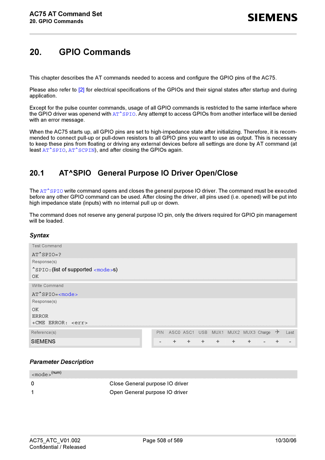
Gpio Commands
Atspio General Purpose IO Driver Open/Close
ATSPIO=?
ATSPIO=mode
Atscpin Pin Configuration
ATSCPIN=?
ATSCPIN=mode, pinid, direction, startValue
Pinidnum
StartValuenum
Atscpol Polling Configuration
ATSCPOL=?
ATSCPOL=mode, ioid
Unsolicited Result Code Scpol ioid, value
AC75 AT Command Set
Atscport Port Configuration
ATSCPORT=?
Scport portid
Portidnum
ATSDPORT=?
Atsdport Delete a Port Configuration
ATSDPORT=portid
ATSGIO=ioid
ATSGIO=?
Sgio value
ATSSIO=?
ATSSIO=ioid, value
Atsccnt Configure Pulse Counter
ATSCCNT=?
ATSCCNT?
Sccnt action, mode, limit
Using the Pulse Counter in Limit Counter Mode
Limit
ATSSCNT=?
Atsscnt Start and Stop Pulse Counter
ATSSCNT?
Using the Pulse Counter in Start-Stop Counter Mode
Java related Commands
Atsjra Run Java Application
ATSJRA=?
ATSJRA=appName
ATSJNET=?
Atsjnet Set Dialup Network Access Parameters
ATSJNET?
Timeoutnum
Bearer servicestr+CSCS
Entry pointstr+CSCS
Authentication mode for CSD and Gprs is always PAP
Atsjotap Over The Air Application Provisioning
ATSJOTAP=?
ATSJOTAP?
Atsjotap
HTTPUserstr Http user name HTTPPwdstr Http password
ApplDirstr
Deststr
Netuserstr
Connect Jsec Ready Send Command
Atsjsec Write Binary Java Security Data
ATSJSEC?
Atsjsec
Certificate contentstr
Untrusted domainnum
Miscellaneous Commands
22.1 A/ Repeat previous command line
ATS3?
22.2 ATS3 Set command line termination character
ATS3=n
ATS4?
22.3 ATS4 Set response formatting character
ATS4=n
ATS5?
22.4 ATS5 Write command line editing character
ATS5=n
Atsfdl Enter Firmware Download Mode
ATSFDL=?
Atsfdl
ATSFDL=mode
OTA Firmware update Over-The-Air
Restricted access to SIM data after SIM PIN authentication
Appendix
AT+CPBW=50,+4030123456789,145,Paul
AT+CPBR=50,50
Imei OK
Star-Hash *# Network Commands
See AT+CLIR
FAX SMS SMS+FAX
Star-Hash Command Response Parameters
Available AT Commands and Dependency on SIM PIN
ATDmemn ATDn ATDstr
ATO
AT+CHLD AT+CLIP AT+CLIR AT+COLP AT+CPUC AT+CSSN AT+CUSD
ATH ATS0
AT+CSIM Atsatr Atsxsm Atscks Atsset Atscid AT+CXXCID
Atsnfpt Atsnfs Atsnftty Atsnfv Atsnfw Atsrtc
AT\Q AT&C AT&D AT&S ATE AT+ICF AT+IFC
ATA ATD
ATS10 ATO
ATD*99#
AC75ATCV01.002 550 10/30/06 Confidential / Released
AT+CRSM AT+CSIM Atsatr Atsxsm Atscks Atsset Atscid AT+CXXCID
ATS3 ATS4
ATS5 Atsfdl
AT Command Settings storable with AT&W
Mode, mt, bm, ds
Service
Show
ATS0 Atslcc AT+CR
Factory Default Settings Restorable with AT&F
Service=3
Service=0
Format=0 View=0, line=1
=0, m=0
=0, p=0
Summary of Unsolicited Result Codes URC
Smgo mode
+CGREG stat
Srsm RsaDevId, RsaMsgId, RsaMsgData, RsaMsgLen, RsaMs
GRc
Sctma m
Sctmb m
Scpol ioid, value
Sccnt time
Alphabetical List of AT Commands
AT+CHLD
AT+CSCA
Atsatr
Atsjnet
ATD*99#
ATD*98#
ATDmemn
ATS3