DEFINING THE NETWORK CONFIGURATION
Table 4-8 Map Add New Object Dialog Box
Attribute | Description | Example |
|
|
|
Protocol | The network protocol of UDP/IP or IPX. | UDP |
|
|
|
Polling Interval | The interval between polling (in seconds). Setting a low value (2 seconds | 5 |
| or less) will generate excessive network traffic and make EliteView seem |
|
| very slow and unresponsive. While a very high value will make EliteView |
|
| insensitive to changes in device status. |
|
|
|
|
Timeout | After sending an SNMP request, EliteView will wait for an appropriate | 3 (values greater than |
| response (in seconds). If the device does not respond before the | 3 are supported, but |
| specified timeout, EliteView will assume that the device is no longer | not recommended) |
| accessible. |
|
|
|
|
Retries | When a device does not respond within the Retries limit, the device is | 10 |
| assumed to be |
|
| the icon turns red. EliteView will continue polling for responses (unless |
|
| Monitor is turned off, as described for the next parameter). |
|
|
|
|
Monitor | If this box is checked, then it will be polled at the specified time interval. | Yes (checked) |
| If this box is not checked, then polling is disabled. Note that the |
|
| resources of the network management station may become overtaxed if |
|
| you attempt to monitor an excessively large number of stations. |
|
|
|
|
Sample Configuration
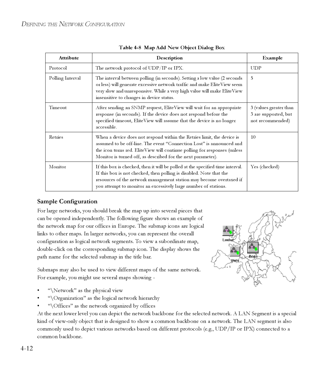
For large networks, you should break the map up into several pieces that can be opened independently. The following figure shows an example of the network map for our offices in Europe. The submap icons are logical links to other maps. In larger networks, you can represent the overall configuration as logical network segments. To view a subordinate map,
Submaps may also be used to view different maps of the same network.
For example, you might use several maps showing -
•“\Network” as the physical view
•“\Organization” as the logical network hierarchy
•“\Offices” as the network organized by offices
At the next lower level you can depict the network backbone for the selected network. A LAN Segment is a special kind of
