AT&T
To Order Copies of this Document Refer to Document Number
Customer Warning
Symbol
Following Symbols and Pictographs Appear on the Equipment
FCC Notification and Repair Information AT&T System
Repair Instructions
OL13C
Private Line Service
ESF
Security of Your SYSTEM-PREVENTING Toll Fraud
FCC Warning Statement
Page
Page
Contents
Power UP and Initialize System
Install CUSTOMER’S S a T
Install Attendant Console
Install Starlan Network Interface
Test Outgoing Trunks
Install Paging System Interface
Maintenance
Error LOG
Routine Maintenance
Error Messages
References Abbreviations and Acronyms
Glossary D E
Figures
November
Tables
MET
Introduction
Introduction
FCC Precautions
Installation
Installation
Tools and Test Equipment
CROSS-CONNECT Equipment Description
10B Emergency Transfer Unit ETU
700A- 110-M-25 or 700A-66-B1-25 157BF Cut-Down Jack
B ETU
Installation Centers are 8-1/2 APART, Flanges Overlapped
617A Panel
Station Interconnect Panel SIP
A Panel
Installation Mounting Centers When Flanges are Overlapped
Adapters
ADAPTER858A Adapter
Fanning Strip
Mounting Centers When Flanges are Overlapped
Cables
Octopus Cables
Connector Connector O
Cable Labels
AT&T
Symbols Used in Figures
Preinstallation Requirements
Restricted
Grounding
AC Power
Lightning Protection
Installation
Secondary Protection
AC Power Distribution-Multiple Cabinet System
Building Wiring
Check Cabinet Contents
Install System Cabinets
Position Cabinets
ZTN77
ZTN78
ZTN79
ZTN76
Installation
10. Three-Cabinet System, Front View With Covers Removed
11. Position of Shorting Plugs on CPU/Memory Circuit Pack
Required Circuit Pack Positions
Label Connectors on Back Cover
Slot
12 a Retainer Clip Installation
Install 4A Retainer Clips
TDM Bus Connections
Connect Cabinets
Installation
13. TDM Bus Terminations Rear View of 3-Cabinet System
Connect Power
Power UP and Initialize System
Ground Wire Connections
ZTN129 CPU/MEMORY CP
Connect Administration Equipment
Cold Start the System
Installation
Illegal
Cold Start
Restart
Slot Cabinet Cabinet 2 Cabinet ZTN85
Check Performance of Cabinet Components
Circuit Pack Type LEDs if Normal LEDs if Failed
Installation
15. Typical System 25 Port Circuit Pack
Report Problems
Initialize System
Install CROSS-CONNECT Equipment
Install TAE, 617A Panels, and Fanning Strips
16. SIP and TAE Backboard Layout
17. Alternate SIP and TAE Backboard Layout
Mount 858A or 2210A2 Adapters
18. Mounting Adapters
Clip
Connect Network Interfaces to TAE Blocks
Install Equipment Room Trunk Cabling
Installation
Connect Ground Start, Loop Start, and did Trunks
Connect Cabinets to TAE Blocks
Connect Tie Trunks
Connect S25 to Another On Premises PBX
Install DS1
19. Direct Connection Side by Side
22. DS1 connections-4311 Feet or More
Off Premises Non Metallic Connections
Off Premises Metallic Cable Connections
24. DS1 Connections-Non Metallic Connections
Install Customer Service Unit CSU
Line Compensation/Equalization
Connect Coupled Bonding Conductor CBC
Installation
Install Equipment Room Station Cabling
Installation
Modular Plug Termination
27. Modular Plug Terminations Connected to the SIP
Pair Cable Terminations
28. Cut Down Terminations Connected to the SIP
Terminal Type
Nstallation
Prepare Carrier Loading Labels
Installation
Modify Octopus Cables if Required
30. Standard and Modified Octopus Cables
Make SIP Connection for CPU/Memory
31. Mounting Octopus Cable on Fanning Strip
Make SIP Connections to Cabinet for 7300H Series Terminals
Make SIP Connections to Cabinet for MET Sets
74a
Make SIP Connections for Data Terminals and Computers
Perform SIP Housekeeping
Make SIP Connections to Cabinet for ATL Cordless Telephones
Install Emergency Transfer Units ETUs
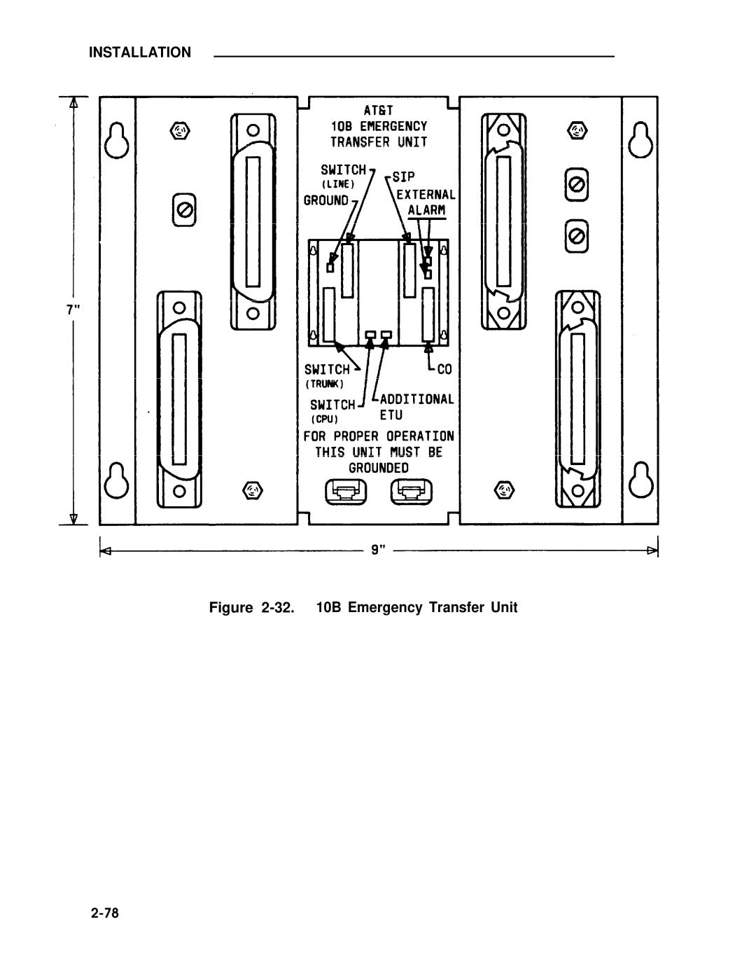
32 B Emergency Transfer Unit
33. Emergency Transfer Unit Connections
Connect Trunk Lines From Cabinet to ETU
Make Emergency Transfer Connections
Installation
34. Ground Start Key Installation
Install Ground-Start Key
Install Attendant Console
35. Attendant Console With DXS Console
Installation
36. Remotely Powered DXS Console Connection
Install Terminals
Label Terminals
Feature Button Abbreviations and Labels Contd
Stand-Alone Voice Terminals
TYPICAL-103A Connecting Block
38. Stand-Alone Remotely Powered Voice Terminal Connections
Stand-Alone Remotely Powered Voice Terminals
Installation
39. Single-Line Terminal/ADU Connections
40 HSeriesTerminal/ADU Connections
ATL Cordless Telephone
Off-Premises Stations TN742, TN746B in R3V2
Out-of-Building Voice Terminals ZTN79
41. DS1 to D4 Connections for Off-Premises Stations
ADU Connections
Stand-Alone Data Terminals
C1 -MODULAR Cord D8W-87
42. Local Powering of an ADU
EIA Cord
Installation TN726 -DATA Line CP
W1 -4-PAIR Inside Wiring Cable
C7-MODULAR Cord D6AP-87
TN726 Data Line CP
Madu Connections
Install CUSTOMER’S SAT
Page
Nonswitched Connection of Equipment
Depending on EQUIPMENT, ADU MAY Require Auxiliary Power
On-Premises Digital Switched Connection
Installation
B1 Typical 103A- Connecting Block cl Modular Cord D8U-87
Off-Premises Switched Connection
CO or Provate Line Circuit
Install Station Message Digital Recording Smdr Equipment
Install CUSTOMER’S DTU
49. ZTN84 Starlan Interface CP Connection 112
Install Starlan Network Interface
Single-Line Voice Terminals
Shared System 25 Voice/STARLAN Network Data Connections
50. Single-Line Analog Terminal/STARLAN
73001H Series Voice Terminals
A2 KS-23475 Adapter
FCC-Registered Music Source Interface
Install MUSIC-ON-HOLD Interface
TIP Ring CP
Typical 103A Connecting Block
W1 Inside Wiring Cable MOH KS-23395 Interface
Analog Line CP
53. Music Source, Non-FCC Registered 119
Non-FCC Registered Music Source Interface
53a. Music-on-Hold November
119b
C5 Modular Cord D4BU-87
Install External Alerts
Install Dictation System Interface
Install Recorded Delay Announcement
Install Paging System Interface
Direct Connection to TN763 Auxiliary Trunk CP
55. Paging System Connection to TN763 Circuit Pack 123
Connection to TN763 Auxiliary Trunk CP 278A Adapter Required
55a. Loudspeaker Paging with Background Music November
124b
278A Term 103A Term
C5 Modular Cord D4BU-87 C6 SINGLE-ENDED Modular Cord
Installation TN763 Auxiliary Trunk CP
Page
128
Installation ZTN76 Ground Start C’ ZTN77 Loop Start C’
Installation
59. Paging System Connection to ZTN76 or ZTN77 131
Test DS1 Interface
Test Outgoing Trunks
System Tests
Test Incoming TIE Trunks
Test Incoming did Trunks
Test 7300H Series Voice Terminals
System Tests
Test SINGLE-LINE Voice Terminals
ARS and Smdr Tests
Test Dial Access Codes
Test System Features
Test ATL Cordless Telephone
DGC Test
Call Coverage Test
PDC Login Test
Test Selector Console
Test Attendant Console
Test Data Terminal Dialing Feature
Test Transfer to Data
Make Pooled Modem Test Call
Test External Alert Night Service
Test Paging Interface
Test Dictation System Access
Test MUSIC-ON-HOLD
Test Emergency Transfer
Test TOUCH-TONE Receivers
Maintenance
Maintenance
Equipment Needed
Precautions
Circuit Pack LEDs
General Maintenance Information
System Errors and Alarms
Emergency Transfer
November
Description
Attendant Console LED
Maintenance
Maintenance
Maintenance Strategy
S T E M USER-REPORTED
Total System Failures
Port Problems
Common Control Problems
Automatic Maintenance Tests
Station, Wiring, and Trunk Problems
Maintenance Failure
Setting Up the DTU
Using the Digital Tape Unit
Saving Translations
Save Completed Successfully
Verifying Translations
Verify Completed Successfully
Restoring Translations
Restore Completed Successfully
Reseating and Replacing Circuit Packs
Routine Maintenance
Maintenance
Removing and Restoring Power
Restarting the System
YOU are about to Initiate a Cold Start
Yes CP Type Listed #
CP in Slot Port Displayed
C0LD Start O T Cabinet Cabinet 2 Cabinet
Typical Release 2 cold restart SAT message is as follows
Error LOG
Maintenance
R T Board Date Time Name Number Code Occurred Occurred
Most Recent System Errors
Accessing the Error Log From the SAT
Maintenance
Error Messages
Description
Maintenance Error Message
TDM
Bad Ringing Supply Problems
Maintenance Error Message Possible Solution Description
Maintenance Error Message Possible Solution
Electronic
DSP
External Stack Full Starlan
Starlan
Illegal Instruction This error is
SAT
Error Message Possible Solution Description
Memory ROM Checksum Error
Translated or CP inserted into Wrong slot
Missing Check CP slot reseat CP change
ROM
Circuit Test Failed
Trunk Call Dropped a call that
User Forced Warm Start System
Clearing Supply Troubles Sheet 1
Clearing Power Supply Troubles Sheet 2
Clearing CO Trunk Troubles
Clearing 4-Wire Tie Trunk Troubles Sheet 1
Clearing 4-Wire Tie Trunk Troubles Sheet 2
Clearing 4-Wire Tie Trunk Troubles Sheet 3
Clearing 4-Wire Tie Trunk Troubles Sheet 4
Clearing Starlan Interface Troubles
Clearing Tie Trunk Troubles Sheet 1
Clearing Tie Trunk Troubles Sheet 2
Clearing Tie Trunk Troubles Sheet 3
Clearing Tie Trunk Troubles Sheet 4
Clearing Tie Trunk Troubles Sheet 5
Clearing Paging Equipment Troubles
Complete System Failure
Clearing System-Detected Troubles
Common Control Trouble
Fail CPU RAM Test IC26
Fail Card Test Detail
Circuit Pack Trouble
Power Supply Trouble
Frontplane Ribbon Connector Trouble Release 1 Only
+4.80
Starlan ZTN84
Maintenance
AC Power Schematic
Power Supply Protection
Power Supply Replacement
Fan Assembly Trouble
Backplane and Cabinet Trouble
Overheating Trouble
System Cabinet Backplane Wiring Side Sheet 1
System Cabinet Backplane Wiring Side Sheet 2
10. TDM Signal Designations on Cabinet Backplane
11. Power Designations on Cabinet Backplane
Page
BL-W
Pair Connector to Backplane Designations Contd
11a Adapter November
Maintenance
Clearing USER-DETECTED Troubles
Administration Equipment Troubles
Time-Keeping Troubles
Voice Terminal and Wiring Troubles
Voice Transmission Troubles
7300H Series Terminal Troubles
Virtual Facilities Troubles
12. Clearing Virtual Facilities Troubles Sheet 1
12. Clearing Virtual Facilities Troubles Sheet 2
12. Clearing Virtual Facilities Troubles Sheet 3
Trunk Troubles
Outgoing Trunk Problems
Error Log Interpretation Loop-Start Trunks
Incoming Trunk Problems
Error Log Interpretation Ground-Start Trunks
Did Trunks Troubles
Switched Loop Attendant Console Troubles
Maintenance
Clearing Switched Loop Console Troubles Sheet 2
Maintenance
Clearing Switched Console Troubles
Maintenance
For ALL Other Boards
Description Data Default
Circuit PACK-OPTIONS
For TN742 and ZTN78 only
ZTN78
Circuit Actions Pack Type
Page
Fail CPU a R C H Angel Insane Check ZTN85 TERMINATOR?
Maintenance
References
Administration Manual
An Introduction to AT&T System
Reference Manual
Call Management System-lnstallation Guide
Abbreviations and Acronyms
Abbreviations and Acronyms
Page
Appendix a
Appendix a
ATL MET
Denotes high side or ringside of pair
Appendix a System Wiring Tables Table A-B. Building Wiring
Pair Cable
Appendix B
Appendix B
CPU/MEM
Apparatus Code Comcode
CPU/MEM CP
PEC Apparatus Code Comcode
ZTN84
CS6402UOIA
31OO-ORD
ZD8AJ
Description PEC Apparatus Code Comcode
NAU
PEC Apparatus Code Comcode
Description PEC Apparatus Code Comcode
PEC
C6E
Appendix C
Appendix C
Add Circuit Pack
Add Cabling
Figure C-1. Typical System 25 Port Circuit Pack
Figure C-2. Tie Trunk TN760B Circuit Pack Option Switches
Set Option Switches on TN760B CP
Preferred
Replace Circuit Pack
Add Cabinet
Page
Add Terminal
Add Trunk
Replace Voice-Only Terminal With Voice/Data Terminal
Add Pooled Modem Circuit Pack
Appendix D
Appendix D
November
Users Guide optional 555-530-706
Appendix E
Port Default Code
ARS
Action
Page
Page
Send ringing to bridged appearances
Action Description
Not Administrable
Pooled Facility
Exclusion
Administrable
Manual Signaling
Personal Line
Call Coverage Group
Automatic Intercom
PDC
Transfer to Data
Flex DSS
Send ALL Calls
Call Coverage Individual
Flexible Direct Station
Position Busy
Alarm
Night Service
Action Description Data
O P
Cancel
Start
Release
Destination
System Access
PORT/PDC
Join
Leave Word Calling
Bridged Access
Directory
Agent Status for CMS
Next
MET Voice Terminals
SINGLE-LINE Voice Terminals
Merlin CS ATL Voice Terminals
Aitendant Voice Terminals
Action Button Type
SYS Access Facility
Signal Auto Icom
PDC Acct Entry Alarm G H T
‘ Refer to page 10-6 of the Administration Manual
November
Flex DSS
SCROLL†
LOOP† ALARM†
SYS Access Flex DSS
SYS Access Flex DSS Acct Entry
†Cannot be changed
S P P
Starlan CP
If the Data Port Type is
† Not administrable for trunk port type codes 901-902 or
FAC
901, 902 not Administrable
November
Only Disconnect
Service alert
Action
A t u r e
For Qualified Systems Technicians only
Page
A r d t y p e
Assign the number of rings before
Hhmm Mmddyy
Outside
ATTENDANT’
DID,IN
Not
Barrier codes are cleared
T a
Slac
For Switched Loop Systems only Call Type Code Default
A C
For Switched Loop Systems only Default Call Type
Action Description T a
AB. DGC Announcement Administration
PDC
Action Description Data
PDC/DDC
Fpdc / DGC
Category Board Description Data
Category Description Data
Wats
Attendant Voice Terminals
DLC
Qualified Systems Technician
Qualified Systems Technician Only
Rims
Form HOUR, Minutes Hhmm Assign a stop time for subpattern 1A
Assign Route 3 for subpattern 1 B a
Assign a 7-digit emergency telephone Digit number Number
900 N11 CO exchange for which a pattern
Action = 1 DATA=
Error Message Description Possible Solution
Appendix F Administration Error Messages
Action = 3 Data =
Error Message Description
1044 Inappropriate request Neither primary nor secondary CAP
CAP
Action = 2 Data = PDC
Action =
Caps
Under Data Port
Under Trunks
Check button range for station type
Station or data port belongs to a
OPX
POS
Check the Administration Manual for
R e a d y
Trying to add a number to a TCA
T e r e d
Are untranslated
E r e
Board type does not exist
R a n g e
Action = 2, Data = PDC
Entered numbers for this zone
Action = 1 Data =
Action = 1 Data = Action = 2 Data = PDC
Error Message Description
Error Message Possible Solution
Error Message Description Possible Solution
Office code exists-list It’s in list
Removed because it’s installed in list
Error Message Possible Solution Description
Error Message Possible Solution Description
Menu = 1 Port
Station happens to be the only DGC group
9035 Inappropriate Request
Incorrect Entry Must be CSS or 9048
Glossary
Glossary
Page
Glossary
Glossary
Glossary
Glossary
Glossary
Specific Feature
Glossary
Page
Glossary
Glossary
Page
Glossary
Glossary
Glossary
Glossary
Index
Index
DS1
Total 4 1
Install SIP 2 4
Panels 617A
Smdr
Took 2-2,4-2
Index