D9412GV2/D7412GV2
Prompt Sub-Prompt
Type Styles Used in this Manual
Table of Contents
Tables
SIA CP-01 Quick Reference
Programming Prompts Directory
Document Name Part Number
Using this Program Entry Guide
Differences between the D9412GV2 and D7412GV2 Features
Literature Referenced
GV2MAIN
Product Handlers
Programming Error Displays
Guide to Programming Options
Programming the Control Panel with the D5200 Programmer
Guide to UL 864 Programming Requirements
Settings Permitted in UL
Recommendation
UL 864 Programming Recommendations Prompt Possible Settings
Phone
Default Blank Selection Up to 24 characters do not enter
For SIA CP-01 Compliance Call Waiting Disable
Phone
Modem IIIa2 Communication
Default Yes Selection Yes or No
Phone Parameters
Modem Format
Conettix D6600/D6100
Point/User Flag
Fail is Yes and CC Trouble Tone is Yes
Alarm On Fail
Phone Supv Time
Dtmf Dialing
Bfsk Duress Code
Routing
Buzz on Fail
Two Phone Lines
Programming a Duplicate Report
Programming Primary and Backup Destinations
Route Number Groups Which Has the Highest Priority?
Enhanced Routing
# Backup Device
# Primary Device
View Events?
Burglar Reports
Fire Reports
Burglar Reports
Fire Reports Selection Report Description
Sending Test Reports
User Reports
Test Reports
User Reports Selection Report Description
Test Reports Selection Description
Diagnostic Reports Selection Description
Relay Reports
AutoFunc Reports
RPS Reports
Point Reports
RPS Reports Selections Report Description
Point Reports Selections Description
User Change Reports Selections Description
Access Reports
Access Reports Selections Report Description
User Chng Reports
Programming a Primary and Backup Destination
Enhanced Routing
Enhanced Routing .4 Enhanced Routing on
RG# Primary Pager
RG# Backup SDI
RG# Backup SDI, and Enhanced
RG# Primary SDI
Programming the Pager Phone Number
Pager Display Fields
Event Priorit Event Description Number
Event Descriptions, Priorities, and Numbers
Power Supervision
Default Selection 1 to 90 Blank and 0 are invalid
AC Fail Time
Default 60 sec Selection 10 to 300 sec in 5-sec Increments
AC Fail Display
AC Fail/Res Rpt
Printer Parameters
## Supervised
## Scope
## A1 through A8 in Scope
RPS Parameters
Log % Full
RPS Passcode
Answer Disarmed
RPS Call Back
RPS Line Monitor
Answer Armed
Miscellaneous
RPS Ph
Duress Type
# Area On
Cancel Report
Area Parameters
Area
Programming Ten-Digit Account Numbers
Programming Account Numbers in 9000 Series Control Panels
Programming Four-Digit Account Numbers
Programming Four-Digit Account Numbers D5200 Programmer
# Exit Tone
# Delay Res
# FA Bypass Max
# Auto Watch
# Duress Enable
# Duress Enable must be set to Yes
Verify Time to 60 sec
# Area Type
Shared Area Arming Sequence
Shared-Area Characteristics Arming a Shared Area
Access Control Readers Assigned to the Shared Area
Disarming a Shared Area
# Burg Pat
# Fire Time
# Fire Pat
# Burg Time
# Single Ring
# Bell Test
Ring
# Acct O/C
# Fail to Open
# Disable O/C in Window
# Area O/C
# Auto Close
Exit Dly Time
If Disable O/C in Window is
# Fail to Close
# Restrictd O/C
# Latest Close Time
Default Selection 0000 to
Arming Features
# Perimeter O/C
D1255 Keypad
Parameter Setup Requirement
To Early Ambush Timer on
# Early Ambush
# Exit Warning must be set to Yes
# Exit Restart
# Arm No Exit
# Exit Warning
# Entry Warning must be set to Yes
# Entry Warning
Keypad Command Center
Cmd Center
CC# Supervised
CC# A1through A8 in Scope
Default Blank Selection To 128, A, B, C, and Blank
CC# Area Assign
CC# Scope
Default Blank Selection 1 to 8, Blank
CC# Entr Cycl Dr
CC# Assign Door
CC# Arm Now Warn
CC# Trouble Tone
CC# Entry Tone
CC# Exit Tone
## Passcode Arm
CC# Close Door
CC# EnhancCmdCtr
CC# Passcode Follows Scope
CC# Abort Display
CC# Cancel Display
CC# Scroll Lock
CC# Menu Key Lock
Area# Acct Is On
Area# Is On
Area# Not Ready
Area# Is Off
See .10.2 Area Text on
Custom Function
CF### Text
CF### Key Strokes
Programming Custom Function Keystrokes
CF### Custom Function Keystrokes
Example
Keypad Programming Choices
Commands
User Interface
Keypad Selections
Mstr Arm Inst
Master Arm Delay
Perim Delay
Watch Mode
View Pt Status
Perim Partial
View Area Stat
View Memory
Chg Passcode
Access Ctl Level
Door Control
Chg Time/Date
User Cmd
Del User
Extend Close
Print Log
Remote Program
Bypass a Pt
Unbypass a Pt
Change Relay
Invisible Walk Test
Service Walk
Display Rev
Change Skeds
Custom Functions
Function 128 through
Authority Level
## Disarm
## Mstr Arm Inst
## Master Arm Delay
## Perim Delay
## Watch Mode
## Fire Test
## View Memory
## View Pt Status
## Walk Test
## Unlock Door
## Send Report
## Door Control
## Cycle Door
## Chg Passcode
## Access Ctl Lvl
## Chg Display
## Chg Time/Date
## View Log
## Del User
## Extend Close
## User Cmd
## Display Rev
## Reset Sensors
## Change Relay
## Remote Program
## Invisible Walk Test
## Service Walk
## Default Text
## Change Skeds
## Area O/C
## Perimeter O/C
## C Function 128 through
## Force Arm
Level or L## Disarm Level authority to
## Security Level
## Disarm Level
## Function Level
Menu Item
#6 Watch Mode
Default Refer to the program record sheet Selection
Function List
## CC Address 1 through
Relay Parameters
# Alarm Bell
# Reset Sensors
Area Relays
# Area Armed
# Watch Mode
# Area Fault
# Force Armed
# Duress Relay
# Perim Fault
# Silent Alarm
Ground Fault Detect
Summary Fire Tbl
Summary Alarm
Phone Fail
Comm Fail
Summary SupBurg
Summary Trouble
Pass Code or Token Worksheet
Bsfk User Code Report
User ###
Reporting and Logging
User pass code User token or card
### Passcode
### User Group
### Area 1 through Area 8 Auth
### SU1 through SU3 Site
### Name
### Mstr Site
### Mstr Crd Data
Point Index
Point Index
## Type Description Selection
## Type Description
Disarmed is Yes
Normal
Open
Short
Point Responses
Applications for Point Responses 9, D, and E
## Response of 8-9-A-B-C
Example of 24-hour point
## Pt Response
Hour Points
Example of Controlled point
## Silent Bell
## Entry Delay
## Ring Til Rst
## Audible After 2 Failures
## Invisible Pt
Point Response
## Buzz On Fault
Keypad for any fault condition while the point
## Watch Point
Relay Follows Point The relay
## RlyResp Type
## Disp as Dvc
## Local While Disarmed
## Disable Rst
## Local While Armed
## FA Retrnable
5 Open/Close Options
## BP Retrnable
## Bypassable
A# Auto Close prompt
## Cross Point
## Report Bypass at Occurrence
## Fire Point
## Resettable
Parameter Abort Window
## Alarm Abort
Point Number
### Point Index
### BFSK/Relay Codes/Relays
### Area Assign
### Debounce
### BFSK/Relay
CMD7 Point Text
### Point Text
CMD7 Point Index
CMD7 BFSK/Relay
CMD9 Point Index
CMD9 BFSK/Relay
CMD9 Point Text
Windows
Window
# Sunday
# Thursday
# Monday
# Tuesday
# Wednesday
# Open Window Stop
Default Selection Hhmm hours and minutes
Disable O/C in Window is programmed Yes
# Open Window Start
Programming to Link Two Days over Midnight
# Close Early Begin
# Close Window Stop
# Close Window Start
Holiday Indexes for O/C Windows
# Xept Holiday
# Holiday
# Area 1 through
Normal Store Hours
Opening and Closing Windows Worksheet
UW# User Group
User Windows #
UW# Monday
UW# Group Enable
UW# Group Disable
UW# Sunday
Sked Number
Skeds
UW# Xept Holiday
UW# Holiday 1 through
## Function Code
## Area 1through
## Point Number
To 128 for D9412GV2
## Relay Number
Selections Blank
To 128 for D9412GV2 To 64 for D7412GV2
## Defer Status
## Defer Test
## Hourly Report
If Expand Test Rpt in Phone
## Cmd Center
Cmd Center and Custom Func
## Custom Func
## Door 1 through
## Access Ctl Level #
## Access Ctl Level#
## Cmd Center 1through
Access Authority Events
No Entry Events Off
## Monday
## Time
## Date
## Sunday
Date
Holiday Indexes
## Xept Holiday
## Holiday
Index 4 Days
Index 1 Days
Index 2 Days
Index 3 Days
SDI Automation
Enable SDI Auto
Introduction
RPS and D5200 Handler Requirements
RTS Control
Parity/Stop
DTR Control
Supervision
Enable SDI RPS
User Interface Modifications for Command
SDI RPS Parameters
Call Back Enabled
Refer to RPS IP Address
Set RPS IP Address to 0 if Enable Ext
RPS IP Address
RPS Port Number
Programs→Accessories→Communications
For Best Data Smart One
For US Robotics
PC running Remote Programming Software RPS Modem Pstn
External Modem Connection
D9412GV2/D7412GV2 Program Entry Guide 6.0 GV2AUX
Modem Init String
Enable Ext Modem
Default Atdt Selection Not available
Seize Relay
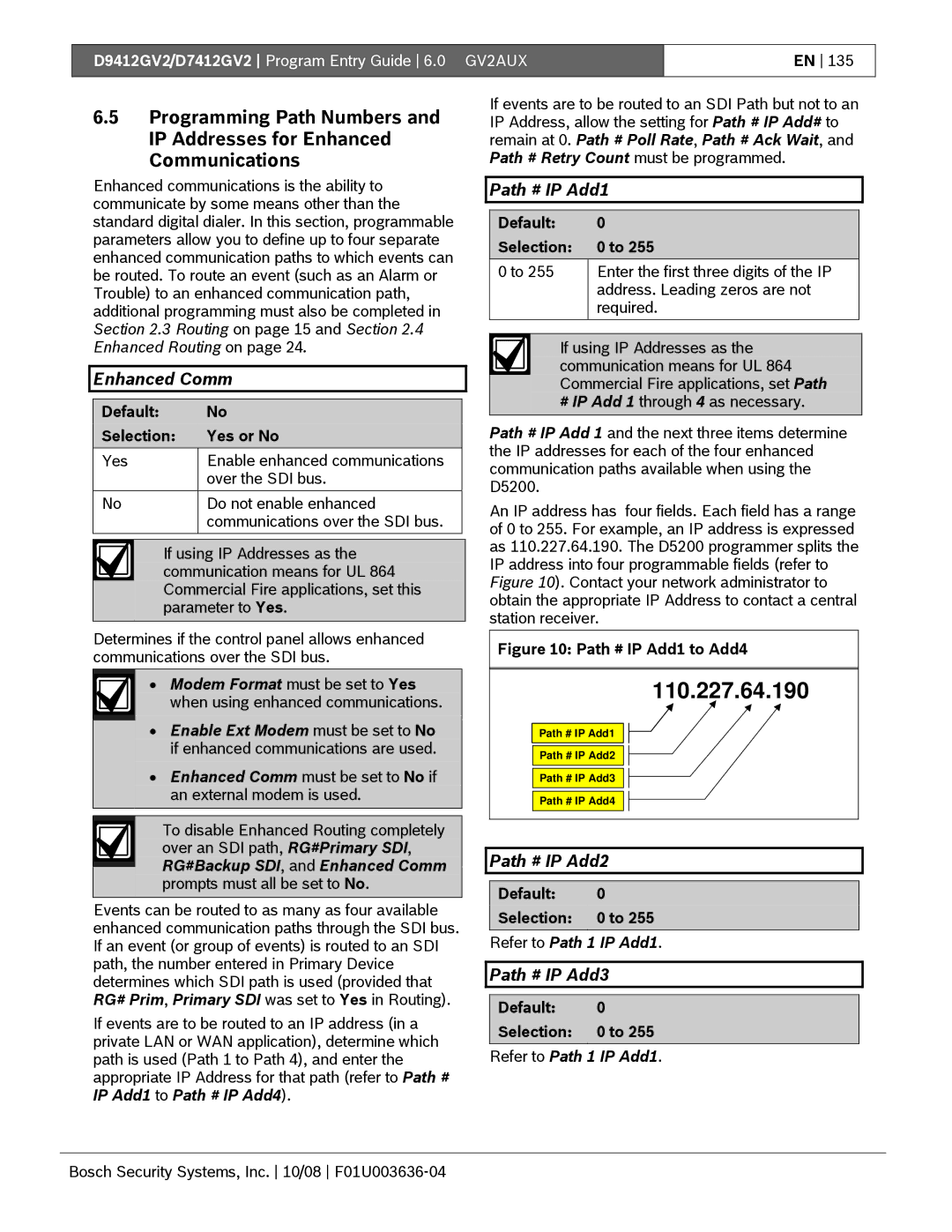
Path # IP Add3
Enhanced Comm
Path # IP Add1
Path # IP Add2
Path # Retry Count is set to
Path # PortNum
Path # Poll Rate
Path # Poll Rate is set to 120 sec
Default Selection Sec to 65535 sec
Path # Ack Wait
Example of Retry Count
Path # Anti-Replay
SDI RPS/Enhanced Communications Configuration
Default Selection 300, 1200, 2400, 4800, 9600, 14.4 K
Path # Retry Count
Route Group Attempts
RG# 1 Attempt
Fire Summary Sustain
Secondary Ambush Code
Enable Protocol Type
Fire Supv Res Type
Fire Trouble Resound
Swinger Count
Default Selection 0, 3, 4, 5, or
Default Selection 3, or
Passcode Length
Early Armed Relay
Cross Point Parameters
CrystalTime Adj
Perimeter Relay
Default 20 sec Selection Sec to 255 sec
Cross Point Time
Cross Point Ranges Within Groups
#CC#Scope
Door Profile
Door #
# Entry Area #
Effects of Programming on Custom Function Activation
Default Blank Selection Blank, 1 to 127, 129 to
# Door Point
# Interlock Point
# Card Type
# Auto Door?
# Fire Unlock?
# Disarm on Open?
# Buzz Time
Strike Profile
# Strike Time
# Shunt Time
# REXShunt Only?
Event Profile
# Deact On Open?
# RTE Shunt Only?
# Exit Request?
# Access Granted?
# No Entry?
# Enter Request?
Programming the Control Panels for SIA CP--01 Compliance
SIA CP-01 Quick Reference
Phone Parameters
Power Supervision
Phone
Printer Parameters
Bell Parameters
Arming Features
Keypad Command Center Assignment51
Access Control Functions
Area Relays
Custom Functions
Point Index
Command 7 and Command 104
Point Assignments 102
Pass Code or Token Worksheet
115
Holiday Indexes 124
144
Bosch Security Systems, Inc /08 F01U003636-04
Bosch Security Systems, Inc. F01U003636-04