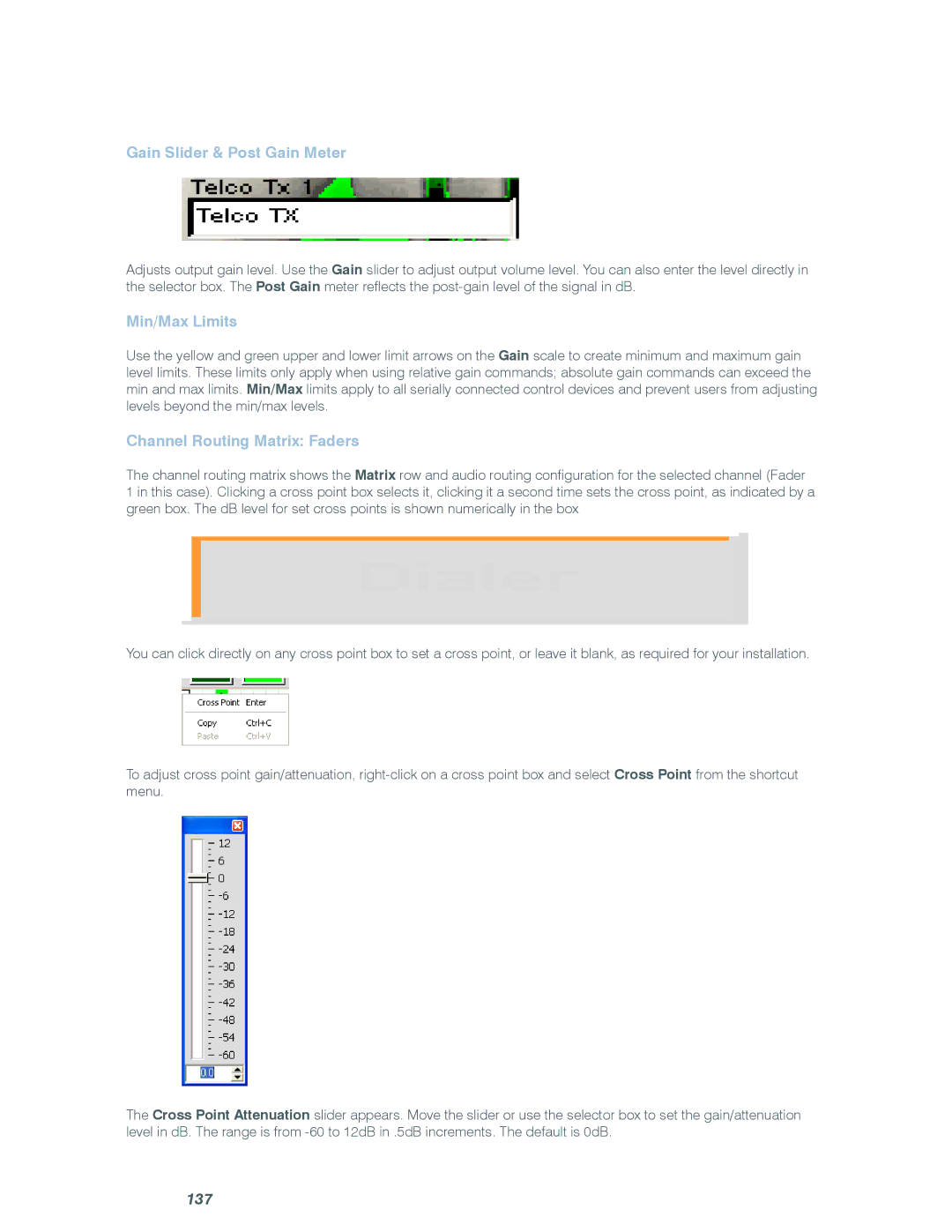
Gain Slider & Post Gain Meter
Adjusts output gain level. Use the Gain slider to adjust output volume level. You can also enter the level directly in the selector box. The Post Gain meter reflects the
Min/Max Limits
Use the yellow and green upper and lower limit arrows on the Gain scale to create minimum and maximum gain level limits. These limits only apply when using relative gain commands; absolute gain commands can exceed the min and max limits. Min/Max limits apply to all serially connected control devices and prevent users from adjusting levels beyond the min/max levels.
Channel Routing Matrix: Faders
The channel routing matrix shows the Matrix row and audio routing configuration for the selected channel (Fader
1 in this case). Clicking a cross point box selects it, clicking it a second time sets the cross point, as indicated by a green box. The dB level for set cross points is shown numerically in the box
You can click directly on any cross point box to set a cross point, or leave it blank, as required for your installation.
To adjust cross point gain/attenuation,
The Cross Point Attenuation slider appears. Move the slider or use the selector box to set the gain/attenuation level in dB. The range is from