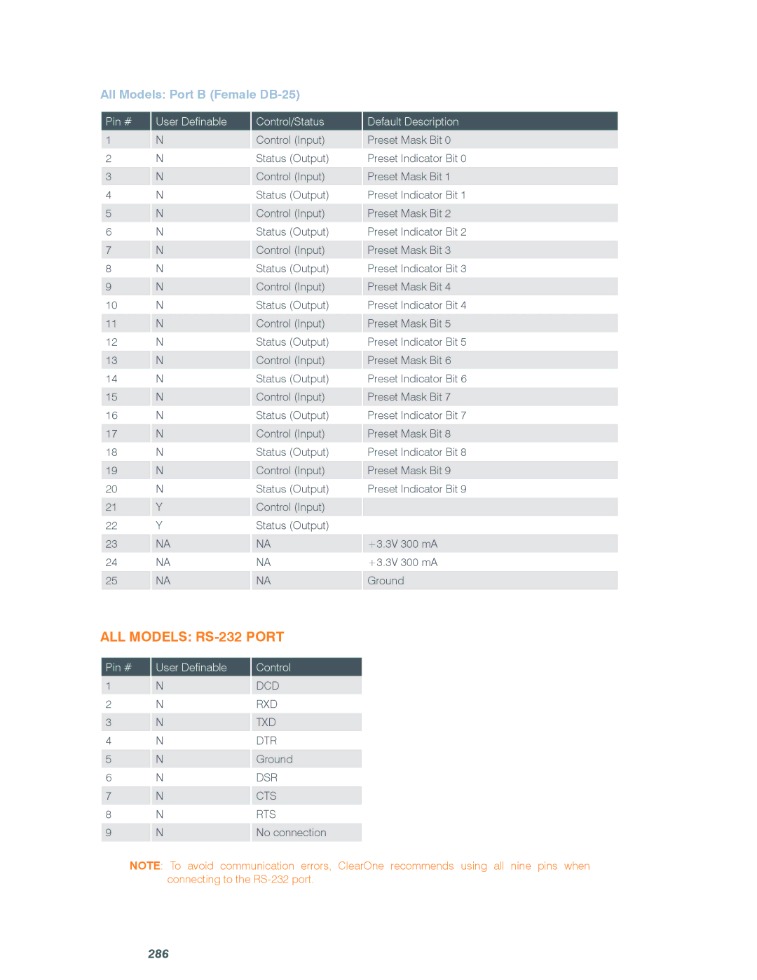
All Models: Port B (Female DB-25)
Pin # 1 2 3 4 5 6 7 8 9 10 11 12 13 14 15 16 17 18 19 20 21 22 23 24 25
User Definable
N
N
N
N
N
N
N
N
N
N
N
N
N
N
N
N
N
N
N
N
Y
Y
NA
NA
NA
Control/Status
Control (Input)
Status (Output)
Control (Input)
Status (Output)
Control (Input)
Status (Output)
Control (Input)
Status (Output)
Control (Input)
Status (Output)
Control (Input)
Status (Output)
Control (Input)
Status (Output)
Control (Input)
Status (Output)
Control (Input)
Status (Output)
Control (Input)
Status (Output)
Control (Input)
Status (Output)
NA
NA
NA
Default Description
Preset Mask Bit 0
Preset Indicator Bit 0
Preset Mask Bit 1
Preset Indicator Bit 1
Preset Mask Bit 2
Preset Indicator Bit 2
Preset Mask Bit 3
Preset Indicator Bit 3
Preset Mask Bit 4
Preset Indicator Bit 4
Preset Mask Bit 5
Preset Indicator Bit 5
Preset Mask Bit 6
Preset Indicator Bit 6
Preset Mask Bit 7
Preset Indicator Bit 7
Preset Mask Bit 8
Preset Indicator Bit 8
Preset Mask Bit 9
Preset Indicator Bit 9
+3.3V 300 mA
+3.3V 300 mA Ground
All Models: RS-232 Port
Pin # 1 2 3 4 5 6 7 8 9
User Definable
N
N
N
N
N
N
N
N
N
Control
DCD
RXD
TXD
DTR Ground
DSR
CTS
RTS
No connection
NOTE: To avoid communication errors, ClearOne recommends using all nine pins when connecting to the
