Channel Routing Matrix: Inputs
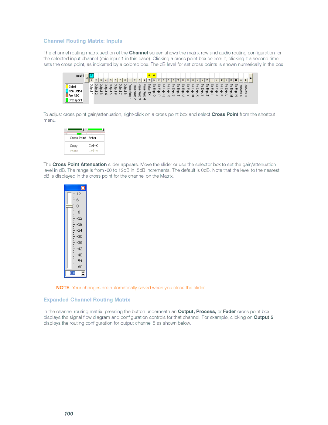
The channel routing matrix section of the Channel screen shows the matrix row and audio routing configuration for the selected input channel (mic input 1 in this case). Clicking a cross point box selects it, clicking it a second time sets the cross point, as indicated by a colored box. The dB level for set cross points is shown numerically in the box.
To adjust cross point gain/attenuation,
The Cross Point Attenuation slider appears. Move the slider or use the selector box to set the gain/attenuation level in dB. The range is from
Note: Your changes are automatically saved when you close the slider.
Expanded Channel Routing Matrix
In the channel routing matrix, pressing the button underneath an Output, Process, or Fader cross point box displays the signal flow diagram and configuration controls for that channel. For example, clicking on Output 5 displays the routing configuration for output channel 5 as shown below.