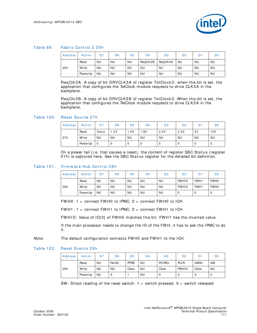
Table 99. | Fabric Control 2 25h |
|
|
|
|
|
|
| ||
|
|
|
|
|
|
|
|
|
|
|
| Address | Action | D7 | D6 | D5 | D4 | D3 | D2 | D1 | D0 |
|
|
|
|
|
|
|
|
|
|
|
|
| Read | NU | NU | NU | ReqClk3B | ReqClk3A | NU | NU | NU |
|
|
|
|
|
|
|
|
|
|
|
| 25h | Write | NU | NU | NU | NU | NU | NU | NU | NU |
|
|
|
|
|
|
|
|
|
|
|
|
| PowerUp | NU | NU | NU | NU | NU | NU | NU | NU |
|
|
|
|
|
|
|
|
|
|
|
ReqClk3A: A copy of bit DRVCLK3A of register TelClock3: when this bit is set, the application that configures the TelClock module requests to drive CLK3A in the backplane.
ReqClk3B: A copy of bit DRVCLK3B of register TelClock3. When this bit is set, the application that configures the TelClock module requests to drive CLK3A in the backplane.
Table 100. Reset Source 27h
Address | Action | D7 | D6 | D5 | D4 | D3 | D2 | D1 | D0 |
|
|
|
|
|
|
|
|
|
|
| Read | Vcore | 1.2V | 1.5V | 1.8V | 2.5V | 3.3V | 5V | 12V |
|
|
|
|
|
|
|
|
|
|
27h | Write | NU | NU | NU | NU | NU | NU | NU | NU |
|
|
|
|
|
|
|
|
|
|
| PowerUp | 0 | 0 | 0 | 0 | 0 | 0 | 0 | 0 |
|
|
|
|
|
|
|
|
|
|
On a power fail (i.e. that causes a reset), the content of register SBC Status (register 01h) is captured here. See the SBC Status register for the detailed bit definition.
Table 101. Firmware Hub Control 28h
Address | Action | D7 |
| D6 | D5 |
| D4 |
| D3 | D2 | D1 | D0 |
|
|
|
|
|
|
|
|
|
|
|
|
|
| Read | NU | NU |
| NU | NU |
| NU |
| FWHID | FWH1 | FWH0 |
|
|
|
|
|
|
|
|
|
|
|
|
|
28h | Write | NU | NU |
| NU | NU |
| NU |
| FWHID | FWH1 | FWH0 |
|
|
|
|
|
|
|
|
|
|
|
|
|
| PowerUp | NU | NU |
| NU | NU |
| NU |
| 0 | 0 | 0 |
|
|
|
|
|
|
|
|
|
|
|
|
|
| FWH0: 1 = connect FWH0 to IPMC; 0 = connect FWH0 to ICH |
|
| |||||||
| FWH1: 1 = connect FWH1 to IPMC; 0 = connect FWH1 to ICH |
|
| |||||||
| FWHID: Value of ID[0] of FWH0 matches this bit; FWH1 has the inverted value | |||||||||
| If the main processor needs to change the ID of the FWH, it has to ask the IPMC to do | |||||||||
| it. |
|
|
|
|
|
|
|
|
|
Note: | The default configuration connects FWH0 and FWH1 to the ICH. |
|
| |||||||
Table 102. Reset Events 29h |
|
|
|
|
|
|
| |||
|
|
|
|
|
|
|
|
|
|
|
| Address | Action | D7 | D6 | D5 | D4 | D3 | D2 | D1 | D0 |
|
|
|
|
|
|
|
|
|
|
|
|
| Read | NU | PwGd | PFRE | NU | PCIREv | PCIR | SWEv | SW |
|
|
|
|
|
|
|
|
|
|
|
| 29h | Write | NU | NU | Clear | NU | Clear | FWHID | Clear | NU |
|
|
|
|
|
|
|
|
|
|
|
|
| PowerUp | NU | X | 1 | NU | X | 0 | X | 0 |
|
|
|
|
|
|
|
|
|
|
|
SW: Direct reading of the reset switch: 1 = switch pressed; 0 = switch released
| Intel NetStructure® MPCBL0010 Single Board Computer |
October 2006 | Technical Product Specification |
Order Number: 304120 | 111 |