MPCBL0010
SWEv: Switch Event: this bit turns to 1 when the reset switch is pressed and stays at ‘1’ until a 1 is written at this bit position. This bit is used to capture a short pulse on the switch.
PCIR: Direct reading of the PCI reset: 1 = PCI reset asserted; 0 = no PCI reset
PCIEv: PCI Reset Event: this bit turns to 1 when a PCI reset occurs and stays in this state until a 1 is written at this bit position. This bit is used to capture a short pulse on PCI_RESET.
SwHw: When set, the reset switch performs a hardware reset independent of the IPMC. When cleared, the IPMC deals with hard/warm resets.
PFREv: Power fail reset event: this bit turns to 1 when a Power Fail occurs and stays in this state until a 1 is written at this bit position. This bit is used to capture a short pulse on the power source. Since power supplies are not valid during a normal
PwrGd: Directs reading of the power good signal that goes to the ICH (and resets everything)
On a
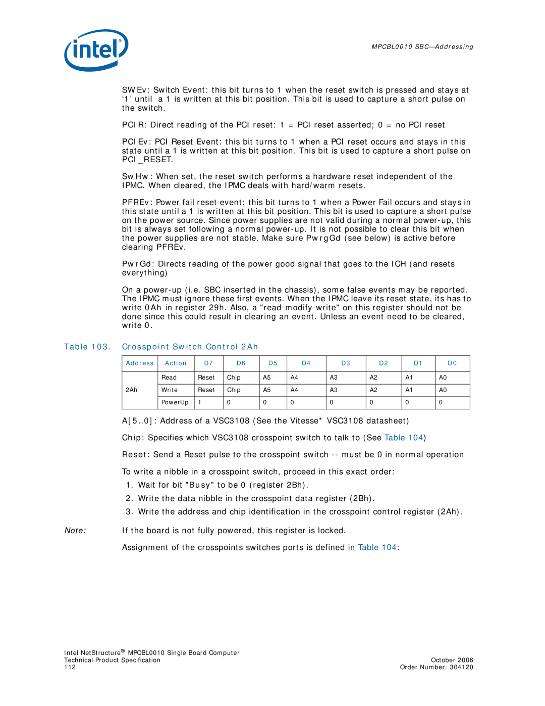
Table 103. Crosspoint Switch Control 2Ah
Address | Action | D7 | D6 | D5 |
| D4 |
| D3 |
| D2 |
| D1 | D0 |
|
|
|
|
|
|
|
|
|
|
|
|
|
|
| Read | Reset | Chip | A5 | A4 |
| A3 |
| A2 |
| A1 |
| A0 |
|
|
|
|
|
|
|
|
|
|
|
|
|
|
2Ah | Write | Reset | Chip | A5 | A4 |
| A3 |
| A2 |
| A1 |
| A0 |
|
|
|
|
|
|
|
|
|
|
|
|
|
|
| PowerUp | 1 | 0 | 0 | 0 |
| 0 |
| 0 |
| 0 |
| 0 |
|
|
|
|
|
|
|
|
|
|
|
|
|
|
A[5..0]: Address of a VSC3108 (See the Vitesse* VSC3108 datasheet)
Chip: Specifies which VSC3108 crosspoint switch to talk to (See Table 104)
Reset: Send a Reset pulse to the crosspoint switch
To write a nibble in a crosspoint switch, proceed in this exact order:
1.Wait for bit "Busy" to be 0 (register 2Bh).
2.Write the data nibble in the crosspoint data register (2Bh).
3.Write the address and chip identification in the crosspoint control register (2Ah).
Note: If the board is not fully powered, this register is locked.
Assignment of the crosspoints switches ports is defined in Table 104:
Intel NetStructure® MPCBL0010 Single Board Computer |
|
Technical Product Specification | October 2006 |
112 | Order Number: 304120 |