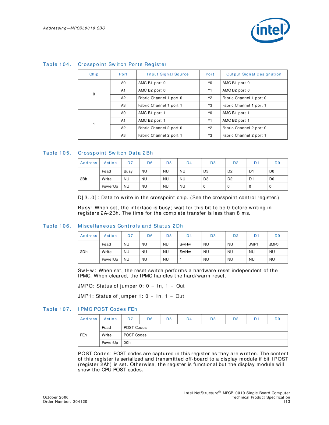
Table 104. Crosspoint Switch Ports Register
Chip | Port | Input Signal Source | Port | Output Signal Designation | |
|
|
|
|
| |
| A0 | AMC B1 port 0 | Y0 | AMC B1 port 0 | |
|
|
|
|
| |
0 | A1 | AMC B2 port 0 | Y1 | AMC B2 port 0 | |
|
|
|
| ||
A2 | Fabric Channel 1 port 0 | Y2 | Fabric Channel 1 port 0 | ||
| |||||
|
|
|
|
| |
| A3 | Fabric Channel 1 port 1 | Y3 | Fabric Channel 1 port 1 | |
|
|
|
|
| |
| A0 | AMC B1 port 1 | Y0 | AMC B1 port 1 | |
|
|
|
|
| |
1 | A1 | AMC B2 port 1 | Y1 | AMC B2 port 1 | |
|
|
|
| ||
A2 | Fabric Channel 2 port 0 | Y2 | Fabric Channel 2 port 0 | ||
| |||||
|
|
|
|
| |
| A3 | Fabric Channel 2 port 1 | Y3 | Fabric Channel 2 port 1 | |
|
|
|
|
|
Table 105. Crosspoint Switch Data 2Bh
Address | Action | D7 |
| D6 | D5 |
| D4 |
| D3 |
| D2 | D1 | D0 |
|
|
|
|
|
|
|
|
|
|
|
|
|
|
| Read | Busy | NU |
| NU | NU |
| D3 |
| D2 |
| D1 | D0 |
|
|
|
|
|
|
|
|
|
|
|
|
|
|
2Bh | Write | NU | NU |
| NU | NU |
| D3 |
| D2 |
| D1 | D0 |
|
|
|
|
|
|
|
|
|
|
|
|
|
|
| PowerUp | NU | NU |
| NU | NU |
| 0 |
| 0 |
| 0 | 0 |
|
|
|
|
|
|
|
|
|
|
|
|
|
|
D[3..0]: Data to write in the crosspoint chip. (See the crosspoint control register.)
Busy: When set, the interface is busy; wait for this bit to be 0 before writing in registers
Table 106. Miscellaneous Controls and Status 2Dh
Address | Action | D7 |
| D6 | D5 | D4 |
| D3 |
| D2 | D1 | D0 |
|
|
|
|
|
|
|
|
|
|
|
|
|
| Read | NU | NU |
| NU | SwHw | NU |
| NU |
| JMP1 | JMP0 |
|
|
|
|
|
|
|
|
|
|
|
|
|
2Dh | Write | NU | NU |
| NU | SwHw | NU |
| NU |
| NU | NU |
|
|
|
|
|
|
|
|
|
|
|
|
|
| PowerUp | NU | NU |
| NU | 1 | NU |
| NU |
| NU | NU |
|
|
|
|
|
|
|
|
|
|
|
|
|
SwHw: When set, the reset switch performs a hardware reset independent of the IPMC. When cleared, the IPMC handles the hard/warm reset.
JMPO: Status of jumper 0: 0 = In, 1 = Out
JMP1: Status of jumper 1: 0 = In, 1 = Out
Table 107. IPMC POST Codes FEh
Address | Action | D7 |
| D6 | D5 | D4 | D3 | D2 | D1 | D0 |
|
|
|
|
|
|
|
|
|
|
|
| Read | POST Codes |
|
|
|
|
|
|
| |
|
|
|
|
|
|
|
|
|
| |
FEh | Write | POST Codes |
|
|
|
|
|
|
| |
|
|
|
|
|
|
|
|
|
| |
| PowerUp | 00h |
|
|
|
|
|
|
| |
|
|
|
|
|
|
|
|
|
|
|
POST Codes: POST codes are captured in this register as they are written. The content of this register is serialized and transmitted
| Intel NetStructure® MPCBL0010 Single Board Computer |
October 2006 | Technical Product Specification |
Order Number: 304120 | 113 |