MPCBL0010
Table 19. Serial Port Connector (J5) Pin Assignments
Pin | Signal |
|
|
1 | RTS |
|
|
2 | DTR |
|
|
3 | TXD |
|
|
4 | GND |
|
|
5 | GND |
|
|
6 | RXD |
|
|
7 | DSR |
|
|
8 | CTS |
|
|
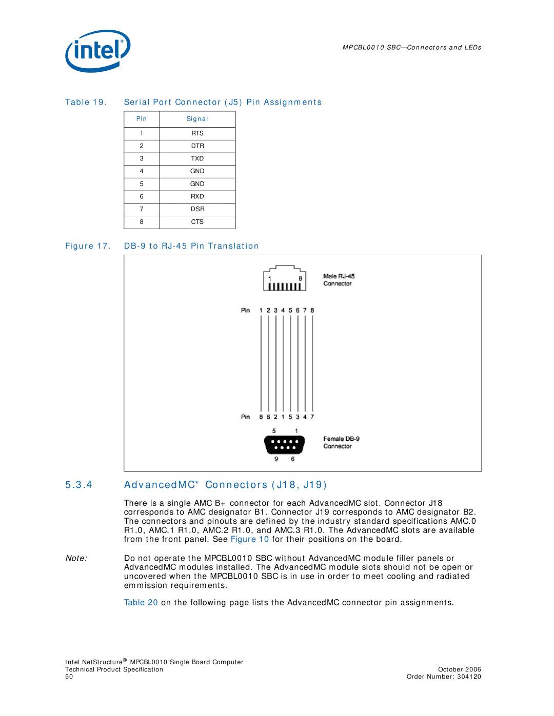
Figure 17. DB-9 to RJ-45 Pin Translation
5.3.4AdvancedMC* Connectors (J18, J19)
There is a single AMC B+ connector for each AdvancedMC slot. Connector J18 corresponds to AMC designator B1. Connector J19 corresponds to AMC designator B2. The connectors and pinouts are defined by the industry standard specifications AMC.0 R1.0, AMC.1 R1.0, AMC.2 R1.0, and AMC.3 R1.0. The AdvancedMC slots are available from the front panel. See Figure 10 for their positions on the board.
Note: Do not operate the MPCBL0010 SBC without AdvancedMC module filler panels or AdvancedMC modules installed. The AdvancedMC module slots should not be open or uncovered when the MPCBL0010 SBC is in use in order to meet cooling and radiated emmission requirements.
Table 20 on the following page lists the AdvancedMC connector pin assignments.
Intel NetStructure® MPCBL0010 Single Board Computer |
|
Technical Product Specification | October 2006 |
50 | Order Number: 304120 |
