Hardware Management
Table 121. Controls Identifier
Control Description | Control Number | |
|
| |
FWH Hub (for BIOS bank information)0 | 0 | |
|
|
|
FWH 0 | Write Protect | 1 |
|
|
|
FWH 1 | Write Protect | 2 |
|
|
|
FWH 0 | Top Block Lock | 3 |
|
|
|
FWH 1 | Top Block Lock4 | 4 |
|
|
|
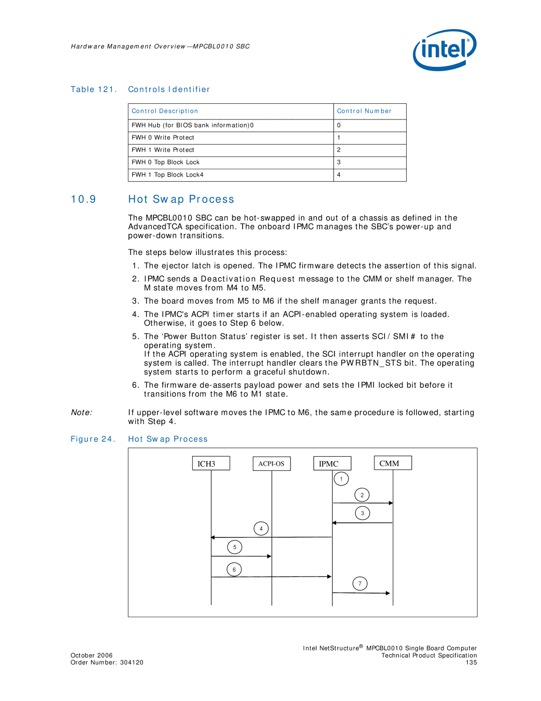
10.9Hot Swap Process
The MPCBL0010 SBC can be
The steps below illustrates this process:
1.The ejector latch is opened. The IPMC firmware detects the assertion of this signal.
2.IPMC sends a Deactivation Request message to the CMM or shelf manager. The M state moves from M4 to M5.
3.The board moves from M5 to M6 if the shelf manager grants the request.
4.The IPMC's ACPI timer starts if an
5.The ‘Power Button Status’ register is set. It then asserts SCI/SMI# to the operating system.
If the ACPI operating system is enabled, the SCI interrupt handler on the operating system is called. The interrupt handler clears the PWRBTN_STS bit. The operating system starts to perform a graceful shutdown.
6.The firmware
Note: If
Figure 24. Hot Swap Process
ICH3 |
| |
|
|
|
4
5
6
IPMC
1
CMM
2
3
7
| Intel NetStructure® MPCBL0010 Single Board Computer |
October 2006 | Technical Product Specification |
Order Number: 304120 | 135 |