Even though authorization is given by the IPMC to drive the clocks to the AdvancedMC module, no actual clocks are driven if the module is not present, unpowered, or illpowered. These bits can be set prior to turning on the AdvancedMC module’s power. A readback will return the state of the bit, but does not reflect the actual clock. In the case of bad power (12VFault = 1, for example), the clock is not driven even if the authorization bit is set. On an AdvancedMC module extraction, these bits are automatically cleared.
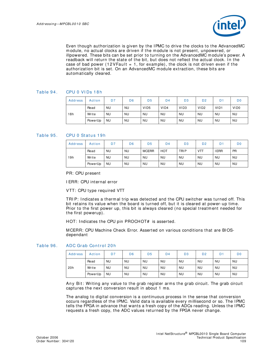
Table 94. | CPU 0 VIDs 18h |
|
|
|
|
|
|
|
| |
|
|
|
|
|
|
|
|
|
|
|
| Address | Action | D7 | D6 | D5 | D4 | D3 | D2 | D1 | D0 |
|
|
|
|
|
|
|
|
|
|
|
|
| Read | NU | NU | VID5 | VID4 | VID3 | VID2 | VID1 | VID0 |
|
|
|
|
|
|
|
|
|
|
|
| 18h | Write | NU | NU | NU | NU | NU | NU | NU | NU |
|
|
|
|
|
|
|
|
|
|
|
|
| PowerUp | NU | NU | NU | NU | NU | NU | NU | NU |
|
|
|
|
|
|
|
|
|
|
|
Table 95. | CPU 0 Status 19h |
|
|
|
|
|
|
|
| ||
|
|
|
|
|
|
|
|
|
|
|
|
| Address | Action |
| D7 | D6 | D5 | D4 | D3 | D2 | D1 | D0 |
|
|
|
|
|
|
|
|
|
|
|
|
|
| Read |
| NU | NU | MCERR | HOT | TRIP | VTT | IERR | PR |
|
|
|
|
|
|
|
|
|
|
|
|
| 19h | Write |
| NU | NU | NU | NU | NU | NU | NU | NU |
|
|
|
|
|
|
|
|
|
|
|
|
|
| PowerUp |
| NU | NU | NU | NU | NU | NU | NU | NU |
|
|
|
|
|
|
|
|
|
|
|
|
PR: CPU present
IERR: CPU internal error
VTT: CPU type required VTT
TRIP: Indicates a thermal trip was detected and the CPU switcher was turned off. This bit retains its value when the board is turned off, but it is cleared at
HOT: Indicates the CPU pin PROCHOT# is asserted.
MCERR: CPU Machine Check Error. Asserted on various conditions that are BIOS- dependant
Table 96. | ADC Grab Control 20h |
|
|
|
|
|
|
| ||
|
|
|
|
|
|
|
|
|
|
|
| Address | Action | D7 | D6 | D5 | D4 | D3 | D2 | D1 | D0 |
|
|
|
|
|
|
|
|
|
|
|
|
| Read | NU | NU | NU | NU | NU | NU | NU | NU |
|
|
|
|
|
|
|
|
|
|
|
| 20h | Write | NU | NU | NU | NU | NU | NU | NU | NU |
|
|
|
|
|
|
|
|
|
|
|
|
| PowerUp | NU | NU | NU | NU | NU | NU | NU | NU |
|
|
|
|
|
|
|
|
|
|
|
Any Bit: Writing any value to the grab register arms the grab circuit. The grab circuit captures the next conversion result in about 1 ms.
The analog to digital conversion is a continuous process in the sense that conversion occurs regardless of the IPMC. Valid data is available every millisecond or so. The IPMC tells the FPGA in advance that wants a fresh copy of the ADCs reading. Unless the IPMC requests a fresh copy, the ADC values returned by the FPGA never change.
| Intel NetStructure® MPCBL0010 Single Board Computer |
October 2006 | Technical Product Specification |
Order Number: 304120 | 109 |
