MPCBL0010
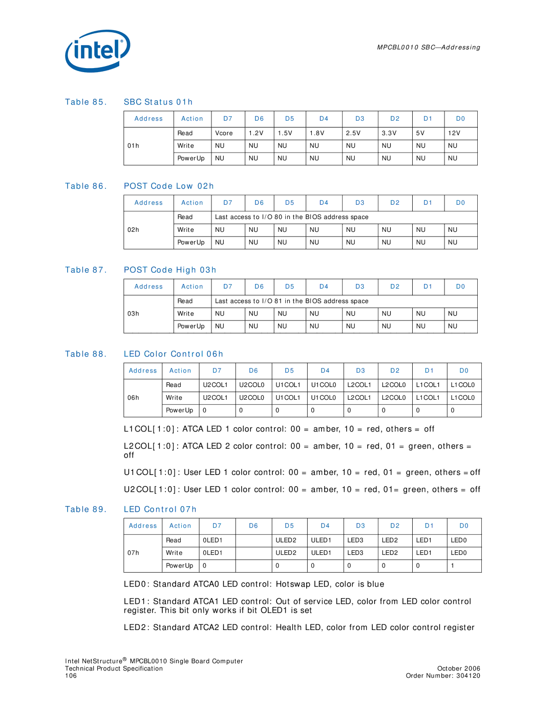
Table 85. | SBC Status 01h |
|
|
|
|
|
|
|
| |
|
|
|
|
|
|
|
|
|
|
|
| Address | Action | D7 | D6 | D5 | D4 | D3 | D2 | D1 | D0 |
|
|
|
|
|
|
|
|
|
|
|
|
| Read | Vcore | 1.2V | 1.5V | 1.8V | 2.5V | 3.3V | 5V | 12V |
|
|
|
|
|
|
|
|
|
|
|
| 01h | Write | NU | NU | NU | NU | NU | NU | NU | NU |
|
|
|
|
|
|
|
|
|
|
|
|
| PowerUp | NU | NU | NU | NU | NU | NU | NU | NU |
|
|
|
|
|
|
|
|
|
|
|
Table 86. POST Code Low 02h |
|
|
|
|
|
|
|
| |||
|
|
|
|
|
|
|
|
|
|
|
|
| Address | Action |
| D7 | D6 | D5 | D4 | D3 | D2 | D1 | D0 |
|
|
|
|
|
|
|
|
|
|
|
|
|
| Read |
| Last access to I/O 80 in the BIOS address space |
|
|
| ||||
|
|
|
|
|
|
|
|
|
|
|
|
| 02h | Write |
| NU | NU | NU | NU | NU | NU | NU | NU |
|
|
|
|
|
|
|
|
|
|
|
|
|
| PowerUp |
| NU | NU | NU | NU | NU | NU | NU | NU |
|
|
|
|
|
|
|
|
|
|
|
|
Table 87. | POST Code High 03h |
|
|
|
|
|
|
| ||
|
|
|
|
|
|
|
|
|
|
|
| Address | Action | D7 | D6 | D5 | D4 | D3 | D2 | D1 | D0 |
|
|
|
|
|
|
|
|
|
|
|
|
| Read | Last access to I/O 81 in the BIOS address space |
|
|
| ||||
|
|
|
|
|
|
|
|
|
|
|
| 03h | Write | NU | NU | NU | NU | NU | NU | NU | NU |
|
|
|
|
|
|
|
|
|
|
|
|
| PowerUp | NU | NU | NU | NU | NU | NU | NU | NU |
|
|
|
|
|
|
|
|
|
|
|
Table 88. | LED Color Control 06h |
|
|
|
|
|
|
|
| ||
|
|
|
|
|
|
|
|
|
|
|
|
| Address | Action | D7 | D6 | D5 |
| D4 | D3 | D2 | D1 | D0 |
|
|
|
|
|
|
|
|
|
|
| |
|
| Read | U2COL1 | U2COL0 | U1COL1 | U1COL0 | L2COL1 | L2COL0 | L1COL1 | L1COL0 | |
|
|
|
|
|
|
|
|
|
|
| |
| 06h | Write | U2COL1 | U2COL0 | U1COL1 | U1COL0 | L2COL1 | L2COL0 | L1COL1 | L1COL0 | |
|
|
|
|
|
|
|
|
|
|
|
|
|
| PowerUp | 0 | 0 | 0 |
| 0 | 0 | 0 | 0 | 0 |
|
|
|
|
|
|
|
|
|
|
|
|
| L1COL[1:0]: ATCA LED 1 color control: 00 | = amber, 10 = red, others = off |
| ||||||||
| L2COL[1:0]: ATCA LED 2 color control: 00 | = amber, 10 = red, 01 = green, others = | |||||||||
| off |
|
|
|
|
|
|
|
|
|
|
U1COL[1:0]: User LED 1 color control: 00 = amber, 10 = red, 01 = green, others =off
U2COL[1:0]: User LED 1 color control: 00 = amber, 10 = red, 01= green, others = off
Table 89. LED Control 07h
Address | Action | D7 | D6 | D5 | D4 | D3 | D2 | D1 | D0 |
|
|
|
|
|
|
|
|
|
|
| Read | 0LED1 |
| ULED2 | ULED1 | LED3 | LED2 | LED1 | LED0 |
|
|
|
|
|
|
|
|
|
|
07h | Write | 0LED1 |
| ULED2 | ULED1 | LED3 | LED2 | LED1 | LED0 |
|
|
|
|
|
|
|
|
|
|
| PowerUp | 0 |
| 0 | 0 | 0 | 0 | 0 | 1 |
|
|
|
|
|
|
|
|
|
|
LED0: Standard ATCA0 LED control: Hotswap LED, color is blue
LED1: Standard ATCA1 LED control: Out of service LED, color from LED color control register. This bit only works if bit OLED1 is set
LED2: Standard ATCA2 LED control: Health LED, color from LED color control register
Intel NetStructure® MPCBL0010 Single Board Computer |
|
Technical Product Specification | October 2006 |
106 | Order Number: 304120 |